


CPRS-1400,1400D INSTALLATION MANUAL
Issue : 2004.07
ED : 0
CPRS-1400,1400D INSTALLATION MANUAL 42 /47
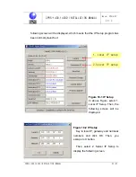
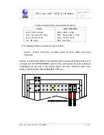
4.3 Normal Operation
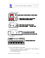
Default setting of the rectifier is FLOAT mode. NORMAL LED and AC LED at the
control panel will be turned on. The LCD window shows various information of the
rectifier (See the Figure). User may check change or status of setup using the
PUSH BUTTON switch at the window.
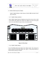
4.3.1 Initial Operation Status Check
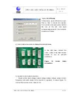
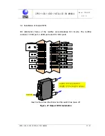
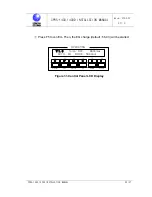
1) Rectifier Module(DRM-4200)
Î
Check if the ON LED is turned on.
Î
Check if STB and ALARM LEDs are turned off.
If the STB LED is ON, communication with the control panel is failed or not
connected. Check the initialization checkpoints again.
Î
Check if fan operates normally.
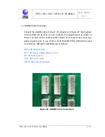
2) Control Panel(CPRC)
Î
Check if the status indication LED turns the NORMAL(Green) on.
Î
Check if output voltage is correctly displayed on the VOLT METER window.
Î
Check if output current is correctly displayed on the AMPERE METER
window. (Depending on load, displayed values may vary. )
Î
Check if the REC TX/RX (Green) is blinking on the RS 232 status indicating
LED window.
Î
Check if there is no alarm signs on the LCD window, and current status is
correctly displayed on the window.
※
Depending on the number of rectifier modules, max current displayed on the
LCD window may be different. (EX: 3 modules
Î
3 X 200A X 110% =
660Amax)
See Figure 31.