background image


23

16.4


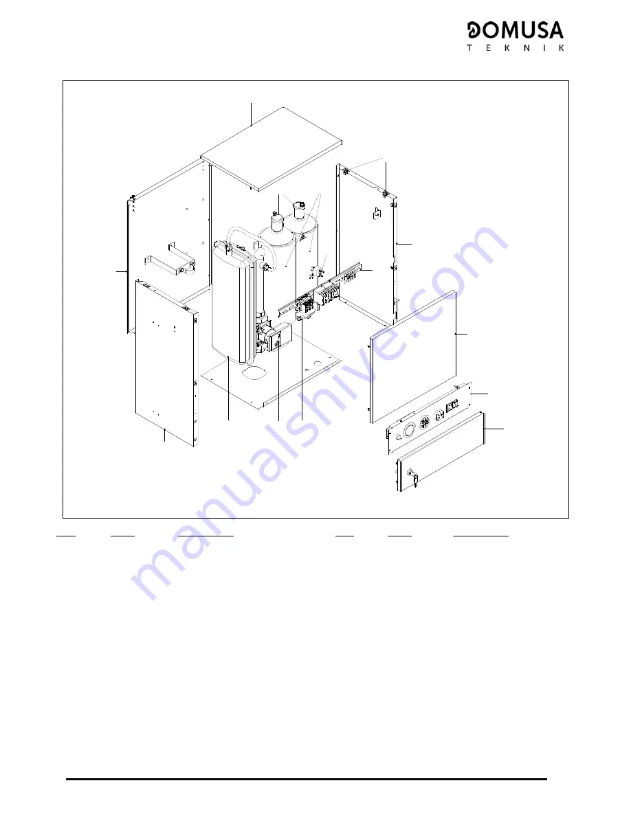
HDEEM 210 


3

1

5

6

7

8

44

13

13

2

1

12

11

10

15

14

14


Pos.


Code


Designation


Pos.

Code


Designation


SEPO000353 

Right side cover


SEPO000030 

Lower front cover 

SEPO000354 

Left side cover 

CFER000026 Lock 

SEPO000355 Back 

cover


10 

CRES000005 

10.5 kW element (210) 

SEPO000032 Top 

cover 

11 

CFOV000145 Heating 

pump 

CFER000048 Spring 

closure


12 

CFOV000032 Expansion 

vessel 

GMANDEE007 

Modular control board (210)


13 

GFOV000002 

Automatic air vent valve


SEPO000031 Door 

14 

SCON000046 Heat 

exchanger 

SELEDEE000 Electrical 

board 

15 

CELC000078 Pressure 

switch 

Summary of Contents for HDEE SERIES

Page 1: ...INSTALLATION AND OPERATING INSTRUCTIONS HDEE HDEEM domusa domusa ER 0170 1996 ER 0170 1996 CGM 04 392 ...

Page 2: ...arnings and recommendations in the manual carefully as they contain important information on the safety use and maintenance of the installation These boilers are to be installed by qualified personnel only following the manufacturer s instructions Only DOMUSA TEKNIK s Authorised Technical Assistance Services are authorised to start up these boilers and carry out any maintenance operations The manu...

Page 3: ...LECTION 7 8 FUNCTIONING WITH TIMER OPTIONAL 8 9 SWITCHING OFF THE BOILER 8 10 BOILER MAINTENANCE 8 10 1 SAFETY DEVICE MAINTENANCE 8 10 2 RECOMMENDATIONS 8 11 DIAGRAMS AND MEASUREMENTS 9 12 CIRCULATING PUMP FLOW CURVES 10 13 TECHNICAL CHARACTERISTICS 11 14 ELECTRICAL DIAGRAM 12 14 1 CONTROL DIAGRAM 12 14 2 POWER DIAGRAM 14 14 3 POWER CABLE DIMENSIONS 16 14 4 CHANGING THE VOLTAGE 16 14 5 CHANGING TH...

Page 4: ...IST OF COMPONENTS HDEE 1 4 5 2 3 7 6 7 3 2 5 4 1 6 HDEEM 1 2 3 4 5 6 7 3 4 5 7 6 1 2 1 Modular control 2 Expansion vessel 3 Automatic air vent 4 Pressure switch 5 Heating Element 6 Heating pump 7 Pressure relief valve ...

Page 5: ...his indicates the temperature and pressure of the heating circuit 4 Boiler control thermostat Allows to select the desired boiler set point temperature to be selected deactivating the element when the set point temperature is reached or keeping it functioning until this is the case 5 Main switch i This is for switching the boiler on and off 6 Power selectors I II These enable the desired heating p...

Page 6: ...ntial to cut off the electricity supply Users must not access internal boiler components or control components 3 3 Applicable legislation It is essential to observe the laws in force regarding electric boiler installation 3 4 Warnings This manual forms an integral part of the appliance it refers to and must be given back to the user Boiler installation and maintenance must be carried out by qualif...

Page 7: ...5 500 500 500 400 200 4 INSTALLATION INSTRUCTIONS Fitting measurements HDEEM HDEE Wall mounting system for HDEEM 300 15 mm ...

Page 8: ...or return heating circuit 4 2 Electrical installation Ensure the voltage in the home is the same as that indicated for the boiler Make the electrical connections in accordance with the electrical diagrams shown in this manual We recommend installing a main switch on the power lines enabling all supply phases to the boiler to be cut off A neutral phase is required to connect the boiler at 400 V 3N ...

Page 9: ...e boiler 6 1 Observations If the boiler does not start up when you have checked that the power is reaching it the installation is filled with water at the correct pressure the circulating pump is turning and the boiler has not been cut out by the safety circuit breaker turn off the main switch and contact the installer 7 OPERATION 7 1 Power setting selection The total power to the boiler may be re...

Page 10: ...h off the boiler turn the main switch to O 10 BOILER MAINTENANCE 10 1 Safety device maintenance Check the thermostats and safety devices are working correctly Check the heating circuit pressure relief valves and the domestic hot water circuit if applicable 10 2 Recommendations Boiler maintenance is recommended at least once a year Maintenance must be carried out by qualified technicians To keep th...

Page 11: ...20 100 540 150 165 50 85 330 450 180 760 IC VS RC V HDEEM 300 330 450 175 640 IC VS RC 155 40 VS RC 40 IC 120 IC Heating Output HDEEM 1 F HDEE 3 4 M RC Heating Return HDEEM 3 4 M HDEE 1 F VS Pressure relief valve 1 2 F V Drain valve 1 2 M ...

Page 12: ...sponding to the three speeds of the circulating pumps and the boiler pressure drop 1 Constant speed I II III traditional mode The pump operates at a constant pre set speed I II III Min 2 Variable differential pressure p v The setpoint value of the differential pressure H increases in a straight line between H and H within the permitted flow margin The differential pressure generated by the pump is...

Page 13: ...W 6x1 5 6x2 5 6x3 6x1 75 6x1 5 6x2 5 6x3 6x1 75 Number of elements 1 1 1 2 1 1 1 2 Water pressure drop mH2O 0 02 0 08 0 1 0 2 0 30 0 38 0 02 0 08 0 11 0 22 0 31 0 46 Resistance value of heating element Ω 35 2 21 1 17 6 30 2 35 2 21 1 17 6 30 2 Expansion vessel volume Litres 7 5 7 5 Maximum operating pressure bar 3 3 Minimum operating pressure bar 0 6 0 6 Maximum operating temperature ºC 90 90 Maxi...

Page 14: ...P C 2 F 4 7 6 2 3 IG PON I1 2 I1 2 1 5 9 10 11 12 5 6 7 8 1 2 3 4 X12 O O BC 9 BC Heating pump TA Room thermostat F Fuse X12 12 way connector for timer Optional IG Main switch I1 2 Half power switch PON On pilot light P1 2 power pilot light TC Heating control thermostat TS Heating safety thermostat P Pressure switch C1 C2 Heating contactors ...

Page 15: ... I1 2 1 5 9 10 11 12 5 6 7 8 1 2 3 4 X12 O O BC 9 BC Heating pump TA Room thermostat F Fuse X12 12 way connector for timer Optional IG Main switch I1 2 Half power switch PON On pilot light P1 2 power pilot light TC Heating control thermostat TS Heating safety thermostat P Pressure switch C1 C2 Heating contactors ...

Page 16: ...DEEM 14 14 2 Power diagram HDEE HDEEM 45 90 HDEE HDEEM 10 15 O 1 L1 L2 L3 a b R1 R3 R5 R2 R4 R6 B C A C1 C2 P1 P2 C1 C2 Heating contactors P1 P2 Heating element units A B C Bridges for heating power selection ...

Page 17: ...15 HDEE HDEEM 180 HDEE HDEEM 210 N L1 L2 L3 R1 R3 R5 R2 R4 R6 C1 C2 P1 P2 C1 C2 Heating contactors P1 P2 Heating element units ...

Page 18: ...gned for the boiler must be adapted to the new voltage To do this before connecting the boiler to the main supply change the position of the terminal strip bridges as shown in the figures below models HDEE HDEEM 45 90 and HDEE HDEEM 10 15 only To remove a bridge loosen the screws holding it in place and then pull it out of its housing Repeat the above procedure in reverse order to replace it When ...

Page 19: ...r kW 3 1 5 4 5 O 1 L1 L2 L3 N L Three phase 400 V 3N 9 kW Terminal L1 L1 A 6 5 6 5 13 Terminal L2 L2 A 6 5 6 5 13 Terminal L3 L3 A 6 5 6 5 13 Terminal 0 N A 0 0 0 Power kW 4 5 4 5 9 O 1 L1 L2 L3 N L1 L2 L3 C B A Three phase 400 V 3N 7 5 kW Terminal L1 L1 A 6 5 6 5 13 Terminal L2 L2 A 6 5 6 5 13 Terminal L3 L3 A 6 5 0 6 5 Terminal 0 N A 0 6 5 6 5 Power kW 4 5 3 7 5 O 1 L1 L2 L3 N L1 L2 L3 C B Three...

Page 20: ...r kW 5 5 10 O 1 L1 L2 L3 N L C Three phase 400 V 3N 15 kW Terminal L1 L1 A 10 85 10 85 21 7 Terminal L2 L2 A 10 85 10 85 21 7 Terminal L3 L3 A 10 85 10 85 21 7 Terminal 0 N A 0 0 0 Power kW 7 5 7 5 15 O 1 L1 L2 L3 N L1 L2 L3 C B A Three phase 400 V 3N 12 5 kW Terminal L1 L1 A 10 85 10 85 21 7 Terminal L2 L2 A 10 85 10 85 21 7 Terminal L3 L3 A 10 85 0 10 85 Terminal 0 N A 0 10 85 10 85 Power kW 7 5...

Page 21: ... 26 Terminal L3 L3 A 13 13 26 Terminal 0 N A 0 0 0 Power kW 9 9 18 O 1 L1 L2 L3 N L1 L2 L3 HDEE HDEEM 210 Stage 1 Stage 2 Total Terminal strip Three phase 400 V 3N 21 kW Terminal L1 L1 A 15 2 15 2 30 4 Terminal L2 L2 A 15 2 15 2 30 4 Terminal L3 L3 A 15 2 15 2 30 4 Terminal 0 N A 0 0 0 Power kW 10 5 10 5 21 O 1 L1 L2 L3 N L1 L2 L3 ...

Page 22: ...15 2 SEPO000362 Back cover 10 CRES000009 18 kW element 180 3 SEPO000026 Top cover 11 CFOV000032 Expansion vessel 4 CFER000048 Spring closure 12 CFOV000145 Heating pump 5 SELEDEE000 Electrical board 13 SCON000043 Heat exchanger 6 SEPO000027 Door 14 CELC000078 Pressure switch 7 CFER000026 Lock GMANDEE100 Modular control 45 90 8 GFOV000002 Automatic air vent GMANDEE102 Modular control 10 15 9 CVAL000...

Page 23: ...0360 Left side cover 9 CVAL000004 Pressure relief valve 2 SEPO000362 Back cover 10 CRES000005 10 5 kW element 210 3 SEPO000026 Top cover 11 CFOV000032 Expansion vessel 4 CFER000048 Spring closure 12 CFOV000145 Heating pump 5 SELEDEE000 Electrical board 13 SCON000045 Heat exchanger 6 SEPO000027 Door 14 CELC000078 Pressure switch 7 CFER000026 Lock 15 GMANDEE07 Modular control 210 ...

Page 24: ...355 Back cover CRES000008 15 kW element 10 15 3 SEPO000032 Top cover 10 CRES000009 18 kW element 180 GMANDEE100 Modular control 45 90 11 CFOV000145 Heating pump GMANDEE102 Modular control 10 15 12 CFOV000032 Expansion vessel 5 GMANDEE005 Modular control 180 13 GFOV000002 Automatic air vent valve 6 SEPO000031 Door 14 SCON000044 Heat exchanger 7 SELEDEE000 Electrical board 15 CELC000078 Pressure swi...

Page 25: ... side cover 9 CFER000026 Lock 2 SEPO000355 Back cover 10 CRES000005 10 5 kW element 210 3 SEPO000032 Top cover 11 CFOV000145 Heating pump 4 CFER000048 Spring closure 12 CFOV000032 Expansion vessel 5 GMANDEE007 Modular control board 210 13 GFOV000002 Automatic air vent valve 6 SEPO000031 Door 14 SCON000046 Heat exchanger 7 SELEDEE000 Electrical board 15 CELC000078 Pressure switch ...

Page 26: ...signation 1 CELC000022 Safety thermostat 110 ºC 1m 2 CELC000007 Control thermostat 1m 3 CELC000177 Extension without timer 4 CELC000002 Thermohydrometer 1m 5 CELC000097 Knob 6 CELC000011 Main switch 7 CELC000079 Power selection switch 8 CEXT000439 Front panel ...

Page 27: ...rvice 18 GENERAL WARRANTY CONDITIONS DOMUSA TEKNIK guarantees the normal operation of its products in accordance with the following conditions and periods of time as from the date of their START UP 1 YEAR for electric and hydraulic elements pumps valves etc 5 YEARS for boiler shells 5 YEARS for Hot Water Tank This warranty does not include those failures produced by misuse or inappropriate install...

Page 28: ... Bº San Esteban s n Ellesmere Port CH65 9BF 20737 ERREZIL Gipuzkoa Tel 0151 909 6222 Tel 34 943 813 899 www domusateknik com DOMUSA TEKNIK reserves the right to make modifications of any kind to its product characteristics without prior notice CDOC001230 CDOC001230 09 16 ...

Reviews: