


18
Ensure that the generator is isolated from the mains power supply and fully depressurised before carrying out
any of the following service procedures.
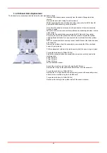
3.4.1 Exhaust Silencer Replacement
The exhaust silencer is located under the inlet manifold assembly. Unscrew the silencer assembly from the exhaust flange plate and
remove.
Slide the silencer element off the baffle
(A)
and replace. Ensure that the replacement element is inserted into the groove of the baffle
end cap.
Screw the exhaust silencer assembly back into the exhaust flange plate.
3.4.2 Oxygen Sensor Replacement
Disconnect the O
2
cell lead from the O2 analyser. Terminals 1 & 2 (% vol O
2
cells) or 4 & 5 (ppm vol O
2
cells)
(B)
Unscrew the tube nut holding the O
2
cell in place and remove the cell
(C)
.
Fit the replacement sensor onto the t-piece and perform a leak test.
Refit the electrical connections to the O
2
analyser:
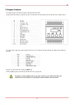
Terminal Function
1
-ve % vol sensor
2
+ve % vol sensor
3 Ground
4
-ve ppm vol sensor
5
+ve ppm vol sensor
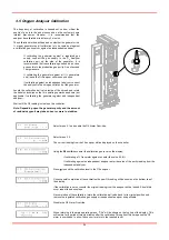
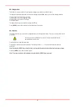
Calibrate the sensor as detailed in section 4.7 (
Note:
PPM cells require the offset value to entered prior to calibrating)
3.4.3 Dust Filter Element Change
Close the buffer vessel outlet valve to isolate the housing and close the “Nitrogen outlet” valve.
De-pressurise the buffer vessel filter by opening the drain valve on the base of the filter. Observe the Nitrogen Outlet Pressure
Gauge, and wait for it to read zero.
If the filter is still pressurised, a high-pitched sound will be heard. If this occurs, stop this procedure
immediately and wait until the filter is completely de-pressurised.
Unscrew the filter bowl from the head
(D)
and remove the old filter element.
Holding the replacement element by the end caps, fit it into the bowl ensuring that the element is correctly seated
(E).
Assemble the filter bowl onto the filter and tighten. The markers on the filter head and filter bowl must line up with each other when
fully assembled
(F)
Close the drain valve on the filter and slowly open the outlet valve of the buffer vessel and the nitrogen outlet valve.
A B C
D E F
Summary of Contents for Maxigas 104
Page 1: ...104 120 SERVICE GUIDE ...
Page 2: ......
Page 4: ......
Page 8: ......
Page 10: ...10 Menu Map ...
Page 11: ...11 ...
Page 14: ......
Page 30: ......
Page 32: ......
Page 33: ...EN 33 APPENDIX A SCHEMATICS ...
Page 34: ......
Page 35: ......


