background image

15

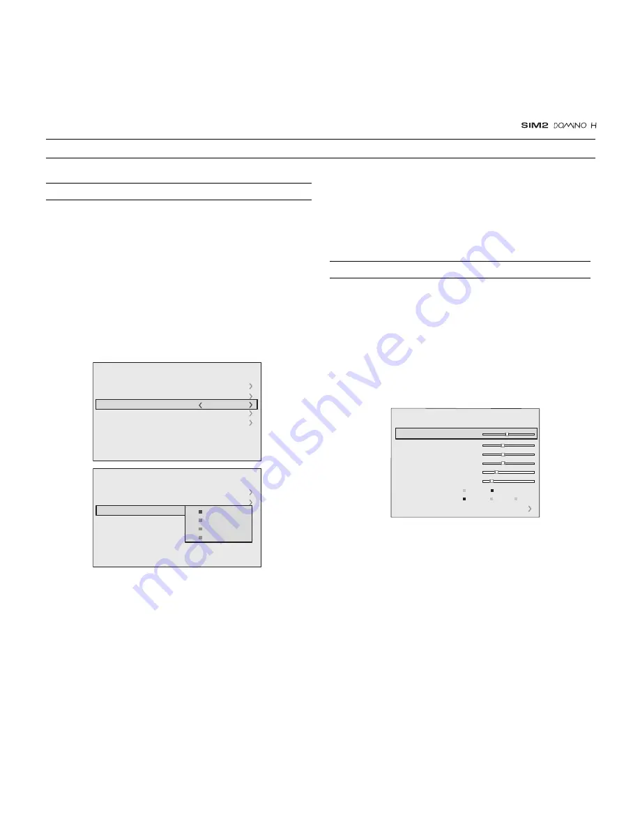
Fig. 26a

Fig. 26b

9  ON SCREEN MENU

After selecting the source signal (by means of the 

 and 

keys), press MENU+/MENU - to confirm and close the pull-
down menu; the value you have just set will be displayed on
the right of the < symbol.
As with the other inputs, you can now select the input just set
by pressing the 

 key.

During the short time it takes to find the signal, a box appears
showing the signal requested. As soon as the signal is shown

INPUTS

The input selection menu (Inputs) is called by pressing 0 on
the remote control and, when no other menu is displayed, using
the 

 and 

 keys on the keypad. To select an input, scroll the

list with the 

 and 

 keys until the desired input is highlighted,

then press 

.

Display of the input selection menu is terminated by pressing
the ESC key, or when the time allowed for displaying the on-
screen menu has lapsed (set in the Set-up Menu).
Input 3 can receive RGB and YCrCb signals, at 15 kHz, 32 kHz
or higher. The association between the input and the type of
signal is made from the pull-down menu that appears on the
right of the < symbol after pressing the 

 key 

(Fig. 26b)

.

in the box additional information is displayed concerning the
video standard (for video signals) or resolution (for graphic
signals), and format.
Fom the SETUP menu it is possible to choose to visualize or not
this information, for more details check the “SOURCE
INFORMATION” in “MENU” section.

The various menus only offer the relevant adjustments in
accordance with the type of input signal displayed (e.g. certain
typical adjustments for video signals, not necessary for graphic
signals, do not appear on the menus, and vice versa).
Some adjustments (e.g. BRIGHTNESS and CONTRAST) are
associated with a numerical value that can be varied within the
set limits using the keys 

 / 

.  For others (e.g. VIDEO TYPE) you

can choose among three options presented on the same
 

 / 

).

Fig. 27

MAIN MENU

To access the main menu of the On Screen Display press the
MENU key on the keypad or the MENU+ or MENU- key on the re-
mote control.
The main menu is divided into four windows, PICTURE,
IMAGE, SETUP and MENU, in which the various adjustments are
grouped according to the frequency of use. Use 

 and 

to select the line corresponding to the adjustment you wish to
make 

(Fig. 27)

.

Picture

Contrast
Color
Tint
Sharpness

Filter
Cinema Mode

Video Type

50

50
50

3

2

Off
Normal

Auto

Auto

VCR1

VCR2

Noise Reduction

Brightness

60

Inputs

1  

VIDEO

2  

S-VIDEO 

3  

COMPONENT/RGBS

4  

GRAPHICS 

RGB

5  

HDMI

1  
2  

5  

15kHz

RGBS 

Inputs

1  

VIDEO

2  

S-VIDEO 

4  

GRAPHICS 

RGB

5  

HDMI

1  
2  

5  

15kHz

RGBS 

   RGBS 15kHz
   RGBS
   YCrCb 15kHz

YCrCb

3  

COMPONENT/RGBS

Summary of Contents for SIM2 Multimedia SpA

Page 1: ...Installation manual cod 46 0338 200...

Page 2: ...projector status VCR Improves the video recorder signals quality ASPECT Selects image Aspect ratio SOURCE Displays the Source Selection menu Up Down Left Right Arrow keys Navigate through and make ad...

Page 3: ...L INPUT AUDIO OUT ZOOM CONTR OL RS 232 GRAPH ICS RGB R Cr G Y B Cb HV 1 2 4 3 5 ATTENTIO N pour ne pas comprome ttre la protection contre les resque d incende remplacer par un fusible de meme type et...

Page 4: ...SIM2 carries out comprehensive functional testing in order to guarantee the maximum product quality For this reason when you start using the product lamp operating hours may already be at between 30...

Page 5: ...omposite video input 16 S Video input 17 VGA input 18 RGB YCrCb input 19 HDMI input 20 Optical Audio Output 21 12Vdc screen output 22 RS232 interface connector 6 4 1 2 3 5 8 7 HDMI AUDIO OUT ZOOM CONT...

Page 6: ...reception which can be determinated by turning the equipment off and on the user is encuraged to try to correct the interference by one or more of the following measures Reorient or relocate the rece...

Page 7: ...ig 4 Do not switch on your projector when flammable liquids or fumes are present Do not pour or drop fluids in the vents Do not use the projector when the room temperature is above 35 C 95 F AUDIO OUT...

Page 8: ...r manual Fig 5 Do not touch the surface of the projection lens The projector must be positioned on a stable suitable platform or be installed using a bracket for fixed ceiling or wall installation Do...

Page 9: ...for more information Use the motorised lens zoom to adjust the image size and the motorised lens focus to achieve maximum clarity With optimum focus you should be able to clearly see each single pixel...

Page 10: ...incende remplace r par un fusible de meme type et de mems caracteris tique CAUTION for continued protection against risk of fire replace only with same type and rating fuse Fig 11 The output is activ...

Page 11: ...er plug Fig 13 Upon switch on in position I the projector will initialise red and green LEDs on Followed by stand by mode red LED on Fig 14 HDMI AUDIO OUT ZOOM CONTROL RS 232 GRAPHICS RGB R Cr G Y B C...

Page 12: ...o type connectors always double check that the plug is inserted the correct way round to avoid damaging the plugs or the sockets on the projector Fig 16 HDMI AUDIO OUT ZOOM CONTROL RS 232 GRAPHICS RGB...

Page 13: ...G B or Y Cr Cb outputs of the source to the respective R Cr G Y B Cb inputs of the projector paying attention not to invert the positions and the synchroni sation signal to the HV input When connecti...

Page 14: ...eo signal The interface also allows the exchange between the video source and the HT system of control data to optimise the quality of the pro jected image The HDMI input allows connection to video so...

Page 15: ...LED on and is de activated when the projector is in stand by mode red LED on The output can be used to control a screen masking system its output can be set with the Screen control adjustment in the...

Page 16: ...es at the same time do not replace one new battery with a used battery If the batteries have leaked carefully wipe the case clean and replace with new batteries The remote control sends commands to th...

Page 17: ...nals or resolution for graphic signals and format Fom the SETUP menu it is possible to choose to visualize or not this information for more details check the SOURCE INFORMATION in MENU section The var...

Page 18: ...ay the signal relative to the grey scale within which the white level and the level immediately below it must be separately identifiable Alternatively use a scene composed of well lit white objects su...

Page 19: ...allows to choose the filter value for noise reduction purposes As soon as this option is selected on the menu the image is divided in two parts In the left side the image is not altered by the filter...

Page 20: ...reframe the screen to a variety of aspect ratios and screen size using an appropriate screen masking inter face connected to the 12 V output socket please refer to the screen manufacture s manual COLO...

Page 21: ...with the AUTO key on the remote control or on the keypad If the automatic procedure fails to have the required effect enter the frequency and phase values manually and approach the screen sufficiently...

Page 22: ...be moved vertically up or down in relation to the centre of the screen the maximum adjustment being equal to half the height of the image in either direction Fig 31 DIGITAL INPUT AUDIO OUT ZOOM CONTR...

Page 23: ...ey it is possible to activate the source Fig 33 The exclusion or activation of the source will automatically renumber the remaining active inputs 2 S VIDEO 4 GRAPHICS RGB 5 HDMI 1 VIDEO 1 2 3 COMP RGB...

Page 24: ...e position represented by horizontal lines Use the and keys to move between letters either left or right respectively Press the numeric key matching the letter Fig 34 the first click of the key select...

Page 25: ...No image Check that the selected input is actually connected to a active video or graphic signal Check that the above source actually works Verify compatibility of video graphic signals with the techn...

Page 26: ...hic image with poor quality vertical detail Verify compatibility of video graphic signals with technical specifications of your projector Press Auto on your remote or keypad to execute automatic adjus...

Page 27: ...000 hours average value measured in the laboratory under optimal condi tions it can be sensibly reduced by the unit misusing OPTICAL DOMINO 30 H Projection system optical engine based on 1 DMD HD2 chi...

Page 28: ...oltage Power Output two 12 Vdc output 100 mA max on jack connectors Output one Optical Audio on TOSLINK connector GENERAL Supply from 100 to 240 Vac 10 6 tolerance Frequency from 48 to 62 Hz Consumpti...

Page 29: ...desired screen size The manual lens shift adjustments allows the projected image to be moved vertically up or down in relation to the centre of the screen Fig 37b If the distance H between the centre...

Page 30: ...80 90 100 120 150 180 200 220 250 in m ft in Screen Screen size width diagonal min L Hmax max L Hmax Min projection distance 16 9 2 7 9 0 3 3 10 9 3 8 12 7 4 4 14 4 4 9 16 2 5 5 17 11 6 6 21 7 8 2 26...

Page 31: ...3 1 9 6 3 2 2 7 3 2 5 8 1 3 0 9 7 3 5 11 3 4 0 13 0 4 4 14 6 4 9 16 2 5 4 17 8 5 9 19 4 7 4 24 3 8 9 29 2 9 9 32 4 50 60 70 80 90 100 110 120 150 180 200 in Screen Screen size width diagonal min L Hm...

Page 32: ...VIDEO Input 11 VGA input 11 RGB YCrCb Input 11 HDMI 12 Motorised projection screen output 12 232 interface connector 13 7 KEYBOARD PAD 13 8 REMOTE CONTROL 14 INDEX 9 ON SCREEN MENUS 15 Source selecti...

Page 33: ...IM2 USA Inc 10108 USA Today Way 33025 Miramar FL USA Phone 1 954 4422999 Fax 1 954 4422998 www sim2usa com e mail sales sim2usa com SIM2 Deutschland GmbH Gewerbepark 17 D 35606 Solms Phone 0800 800 74...

Reviews: