7
EN
L.P. Gas Water Heater Installation
This section describes how to install the Water Heater
and control switch. Please consider the following
directives prior to beginning installation:
• This appliance must be installed by a qualified
professional installer.
• The water heater tank must be supported at the same
level as the bottom of the sidewall cutout. Provide
adequate clearance at the rear of the unit for easy
service access to the water connections.
• If the appliance is installed where a connection or
tank leakage can damage an adjacent area, install a
drain pan (which can be drained outside of the RV)
under the Water Heater.
• To install the Water Heater on carpeting, install
the Water Heater onto a metal or wood panel that
extends at least 3 in. (7.62 cm) beyond the total width
and depth of the Water Heater.
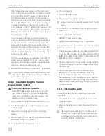
4.1 Preparing the Installation
Location
y
y
q
e
e
t
t
r
r
w
w
3
Preparing the Installation
q
Water Heater
r
Cutout Width
w
Flange
t
Cutout Height
e
Cutout Frame
y
Cutout Depth
1. Plan the location of the Water Heater within the RV.
2. Erect the side walls and cut the square opening.
Refer to the following tables for cutout and clearance
specifications for basic water heater models.
Model
Cutout
Width
Cutout
Height
Cutout
Depth
WH - 6GA
WH - 6GEA
12-7/8 in.
(32.7 cm)
12-7/8 in.
(32.7 cm)
19-1/2 in.
(49.5 cm)
WH - 9GEA
12-7/8 in.
(32.7 cm)
12-7/8 in.
(32.7 cm)
24 in.
(61.0 cm)
WH - 10GEA
WH - 16GEA
16-1/4 in.
(41.3 cm)
15-3/4 in.
(40.0 cm)
20-5/8 in.
(52.4 cm)
25-1/8 in.
(63.8 cm)
The cutout width and height tolerence is
± 1/8 in.
(± 3.0 mm) on all models.
The following table shows the requirements for the
minimum clearance from combustible construction.
Sides
Back
Top
Bottom
0 in.
(0 cm)
0 in.
(0 cm))
0 in.
(0 cm)
0 in.
(0 cm)
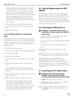
The following figure and table show the minimum
required clearances between the water heater vent
and any projection or plastic part on the side of the
RV.
4
Vent Clearances
Sides
Top
3 in.
(7.62 cm)
12 in.
(30.48 cm)


