3
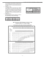
12 VDC
12 VDC
24 VDC
24 VDC
cutout
cutin
cutout
cutin
10.4
11.7
22.8
24.2
TJ18, TJ22, TJ42, TJF42 & TJ80 Installation And Operating Instructions
An overheating of the electronic unit heat sink will
cause the compressor to stop. Restart will occur
automatically when a normal temperature has been
reached.
4.
Voltage Protection
If a voltage outside the operating range is applied
to the electronic unit, the compressor does not start,
or it stops if the voltage limit is exceeded during
operation. The compressor will restart automati-
cally approximately 1 minute after the supply volt-
age has reached the reset voltage within the range
in question.
5.
Battery Protection
The electronic unit provides protection as follows:
Standard Battery Protection Settings
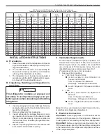
Length of Conductor from Source of Current to Device and Back to Source - Feet
10 15 20 25 30 40 50 60 70 80 90 100 110 120 130 140 150 160 170
Total
Current
On Circuit
In Amps
12 Volts - 3% Drop Wire Size (gauge) - Based on Minimum CM Area
5
18 16 14 12 12 10 10 10
8
8
8
6
6
6
6
6
6
6
6
10
14 12 10 10 10
8
6
6
6
6
4
4
4
4
2
2
2
2
2
15
12 10 10
8
8
6
6
6
4
4
2
2
2
2
2
1
1
1
1
20
10 10
8
6
6
6
4
4
2
2
2
2
1
1
1
0
0
0
2/0
25
10
8
6
6
6
4
4
2
2
2
1
1
0
0
0
2/0 2/0 2/0 3/0
30
10
8
6
6
4
4
2
2
1
1
0
0
0
2/0 2/0 3/0 3/0 3/0 3/0
40
8
6
6
4
4
2
2
1
0
0
2/0 2/0 3/0 3/0 3/0 4/0 4/0 4/0 4/0
50
6
6
4
4
2
2
1
0
2/0 2/0 3/0 3/0 4/0 4/0 4/0
60
6
4
4
2
2
1
0
2/0 3/0 3/0 4/01 4/0 4/0
70
6
4
2
2
1
0
2/0 3/0 3/0 4/0 4/0
80
6
4
2
2
1
0
3/0 3/0 4/0 4/0
90
4
2
2
1
0
2/0 3/0 4/0 4/0
100
4
2
2
1
0
2/0 3/0 4/0
24 Volts - 3% Drop Wire sizes (gauge) - Based on Minimum CM Area
5
18 18 18 16 16 14 12 12 12 10 10 10 10 10
8
8
8
8
8
10
18 16 14 12 12 10 10 10
8
8
8
6
6
6
6
6
6
6
6
15
16 14 12 12 10 10
8
8
6
6
6
6
6
4
4
4
4
4
2
20
14 12 10 10 10
8
6
6
6
6
4
4
4
4
2
2
2
2
2
25
12 12 10 10
8
6
6
6
4
4
4
4
2
2
2
2
2
2
1
30
12 10 10
8
8
6
6
4
4
4
2
2
2
2
2
1
1
1
1
40
10 10
8
6
6
6
4
4
2
2
2
2
1
1
1
0
0
0
2/0
50
10
8
6
6
6
4
4
2
2
2
1
1
0
0
0
2/0 2/0 2/0 3/0
60
10
8
6
6
4
4
2
2
1
1
0
0
0
2/0 2/0 3/0 3/0 3/0 3/0
70
8
6
6
4
4
2
2
1
1
0
0
2/0 2/0 3/0 3/0 3/0 3/0 4/0 4/0
80
8
6
6
4
4
2
2
1
0
0
2/0 2/0 3/0 3/0 3/0 4/0 4/0 4/0 4/0
90
8
6
4
4
2
2
1
0
0
2/0 2/0 3/0 3/0 4/0 4/0 4/0 4/0 4/0
100
6
6
4
4
2
2
1
0
2/0 2/0 3/0 3/0 4/0 4/0 4/0
ABYC Standards - ABYC Guidelines E9 - Direct Current
Conductor Sizes For 3 % Drop in Voltage
See Amp Draw Chart Above To Determine Wire Size
Refrigerator Amperage
Model
Amperage
12 VDC
24 VDC
TJ18, TJ22 & TJ42
3.72
1.86
TJF42 & TJ80
4.56
2.28


