2
SAFETY INSTRUCTIONS
This manual has safety information and instruc-
tions to help users eliminate or reduce the risk of
accidents and injuries.
RECOGNIZE SAFETY INFORMATION
This is the safety-alert symbol. When you see
this symbol in this manual, be alert to the poten-
tial for personal injury.
Follow recommended precautions and safe op-
erating instructions.
UNDERSTAND SIGNAL WORDS
A signal word
,
WARNING
OR
CAUTION
is used
with the safety-alert symbol. They give the level
of risk for potential injury.
indicates a potentially hazard-
ous situation which, if not avoided, could result
in death or serious injury.
indicates a potentially hazard-
ous situation which, if not avoided may result in
minor or moderate injury.
used without the safety alert
symbol indicates, a potentially hazardous situa-
tion which, if not avoided may result in property
damage.
Read and follow all safety information and in-
structions.
!
WARNING
!
CAUTION
CAUTION
!
GENERAL INFORMATION
A. Before installing your Dometic refrigerator, refer to the
Tundra Installation Check List 3309081.0XX located
in the envelope assembly furnished with your Tundra
Refrigerator.
B. This refrigerator is designed for making ice and the
conservation of food and drinks only.
C. All materials exposed to contact with food comply with
EC directive 89/109.
D. Install appliance away from heat sources in a dry and
well-ventilated area. Avoid direct contact with water.
The Refrigerator is not waterproof.
E. This refrigerator complies with
EC directive 89/336
governing radio suppression.
Note:
The data plate bearing the model number, serial num-
ber, and technical data is located on the right-hand side,
inside the refrigerator. An identical data plate is located on
the back of the cabinet.
SPECIFICATIONS
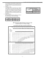
A. Danfoss Compressor Data
1.
Voltage Operating Range
12 VDC systems:
From 10.4 VDC to 17 VDC
24 VDC systems:
From 22.8 VDC to 31.5 VDC
The electronic unit will calibrate automatically to
the applied voltage. This means that if the battery
voltage is less than 17 VDC, the electronic unit as-
sumes that it is working in a 12 VDC System. If the
voltage is higher than 17 VDC, the electronic unit
assumes that it is working in a 24 VDC system.
Consequently, the compressor does not run at
power supply voltages between about 17 VDC and
the desired battery protection cutout voltage (22.8
VDC) for 24 VDC systems.
2.
Protection Systems
The compressor protection system facilitates pro-
tection against compressor overload and start fail-
ure as well as destructive battery discharge. When
an overload protection is activated, the compres-
sor enters a cycle in which it makes start attempts
at approximately 60 second intervals until success-
ful start is achieved.
3. Overload Protections
The compressor overload and start protection cuts
off power to the compressor if the compressor
speed drops below approximately 1,900 rpm, or if
this motor speed is not reached during the start
sequence. Possible reasons for overload protec-
tion activating could be too high refrigeration sys-
tem pressures during operation or lack of pres-
sure equalizing at start.
The fan overload protection stops the compressor
and the fan if the fan current exceeds 0.5 A (aver-
age) or 1 A (peak).
TJ18, TJ22, TJ42, TJF42 & TJ80 Installation And Operating Instructions


