


6
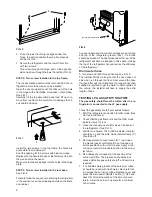
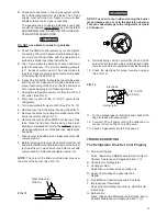
2. Once the lower front strip is slipped under the
hinge, the part is possible to swing into place as
shown in FIG. 6.
3. Secure the refrigerator and the lower front strip
with two screws:
One screw through the hinge, and on the opposite
side one screw through the lower front strip. (FIG. 6).
STEP 2: Two screws installed in the top frame.
The top decoration panel must be removed from the re-
frigerator before the screws can be installed.
Open the door and gently push the tabs out of the hole
in the hinge with a flat blade screwdriver, (both sides).
See FIG. 7.
Carefully tilt the top decoration panel and lift up to re-
move from top frame. Be careful not to damage the cir-
cuit board and wires.
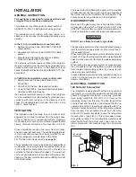
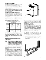
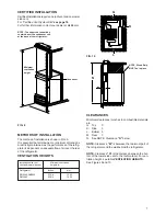
Any space between the counter, storage area or ceiling
and top of the refrigerator greater than 1-1/2 inches
should be blocked. The heat produced at the rear of the
refrigerator will become trapped in this space, making
the top of the refrigerator hot and reduce the efficiency
of the refrigerator.
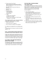
Drain water hose
A hole must be drilled through flooring see FIG. 8.
The installer MUST make sure that the hose does not
kink when run through the floor. Seal around the hose
that goes through the drilled hole. If a longer hose than
supplied is required to get the water to drain outside of
the vehicle, the installer will have to supply the extra
length of hose.
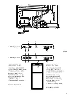
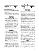
TESTING LP GAS SAFETY SHUTOFF
The gas safety shutoff must be tested after the re-
frigerator is connected to the LP gas supply.
To test the gas safety shutoff, proceed as follows:
1. Start the refrigerator and switch to GAS mode. (See
start up instructions).
2. Check that the gas flame is lit and the GAS mode
indicator lamp (C) is on.
3. Close the manual gas shutoff valve at the back of
the refrigerator. (See FIG. 1).
4. Wait for one minute. The CHECK indicator lamp (E)
should be on and the GAS mode indicator lamp (C)
should be off.
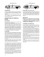
5. Remove protection cover (see FIG. 1) and open
the manual gas shutoff valve. Do not change any
button positions on the control panel. Apply a non-
corrosive commercial bubble solution to the burner
jet orifice.
6. No bubbles should appear at the opening of the
burner jet orifice. The presence of bubbles indi-
cates a defective gas safety shutoff, and service is
required.
7. If no bubbles were present at the burner jet orifice,
it should be rinsed with fresh water. Be careful not
to damage the burner jet orifice. Replace cover and
press the main power ON/OFF button (1) OFF and
back ON. Normal operation of the burner should
return. Allow the burner to operate for a minimum
of 5 minutes.
3
FIG. 6
FIG. 7
1
2
Install the two screws in the top frame, the holes are
accessible from underneath.
Seal the opening for the screws with aluminum tape.
Replace the top decoration panel. Be careful not to pinch
the wires behind the panel.
Make sure the tabs snap back into the holes in the hinge
plate.
STEP 3: Two screws installed in the rear base.
See FIG. 8
Failure to follow the sequence in securing the refrigerator
in the enclosure can cause leakage between the frame
and cabinet.
FIG. 8
Hole for drain water hose
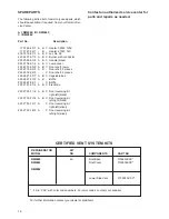
Summary of Contents for RM2662
Page 2: ......
Page 15: ...15...
Page 18: ...18 RM2662 RM2862 RM2663...
Page 19: ...19...
Page 20: ...20 MO FO 0448...