background image

- 9 -

Start the harvest cycle with a flat blade screw driver 

10. 

inserted into the center of the small gear.  


Turn the gear counter clockwise, when the hold 

11. 

switch closes, the mold assembly will continue to 
operate through the harvest cycle. During the water 
fill sequence of the harvest cycle the compressed 
air will blow out the water trapped in the solenoid 
valve. Up to 20 PSIG air pressure can be used to 
clear the solenoid valve.
Repeat the harvest cycle operation several times.  

12. 

RefRIGeRaTOR wITh ICe & waTeR DISPeNSeR:

13. 


Clear the water part of the solenoid valve. 


-

Press the lever to open the valve and then, apply 


-

compressed air to blow out the water trapped in 
this part of the valve.  


Blow out the water from the water dispenser hose. 


-


Reconnect and tighten the lines on water solenoid 

14. 

valve. Make sure that the metal tube is in the plastic 
water line to the ice maker. 
Leave the water supply turned off until temperatures 

15. 

are above 32°f/0°C.
Dry the ice maker mold assembly with a soft cloth.

16. 

Place bail arm in the “UP/Off” position.

17. 

storage procedure / winter operation

To drain the ice maker, follow these steps:

Shut off water supply valve to the ice maker.

1. 

Place a shallow pan under water solenoid valve.

2. 

Remove the hose from the inlet fitting to the water 

3. 

solenoid valve. 

Outlet connection tubing:

• Ice: 1/4” plastic hose

• Water: 5/16” plastic hose

Ice

Water

Inlet fitting 

for water 

supply line

Plastic nut:

• Ice: 7/16” - 20 UNF

• Water: 1/2” - 20 UNF

Water inlet hose

water solenoid valve 

Refrigerator with ice & water dispenser

Inlet fitting for

water supply line

Plastic nut

Metal tube

1/4” Water line

to ice maker

Water solenoid valve

water solenoid valve 

Refrigerator with ice maker or  

ice maker & ice dispenser

Ice Dispenser

Cube   Crush   Light             Lock

WATER

ICE

Apply  

compressed  

air

Drain water from the supply line.

4. 

Remove the plastic nut(s) and water line(s) from 

5. 

outlet side of the water solenoid valve. 
Drain water from the line.  

6. 

Connect compressed air onto the inlet fitting of the 

7. 

water solenoid valve.
Apply AC power to the solenoid valve by forcing 

8. 

the ice maker mold assembly through several har-

vest cycles. Note! Damage to the solenoid can occur 

if AC power is applied for more than 20 seconds.
Remove the plastic cover from the mold assembly. 

9. 

The bail arm must be in the down (“oN”) position. 

Summary of Contents for NDA1402

Page 1: ...e l essence ni d autres vapeurs ou liquides inflamma bles à proximité de cet appareil ou de tout autre appareil Improper installation adjustment alteration service or maintenance can cause injury or property damage Refer to this manual For assistance or additional information consult a qualified installer service agency or the gas supplier Une installation un réglage une modifi cation une réparati...

Page 2: ......

Page 3: ...y hazardous situation which if not avoided may result in minor or moderate injury Used without the safety alert symbol indicates a potentially hazardous situation which if not avoided may result in property damage Information Step by step instructions CAUTION WARNING CAUTION introduction 4 refrigerator overview 4 operating instructions 6 storage procedure winter operation 8 Storage compartments 10...

Page 4: ...ompartments Vacuum insulated panels increase interior storage space Automatic front frame heater prevents condensation from forming on exterior cabinet Flexible storage options Absorption cooling system In an absorption refrigerator system ammonia is liquefied in the finned condenser coil at the top rear of the refrigerator The liquid ammonia then flows into the evaporator inside the freezer secti...

Page 5: ...peratures in the refrigerator current modes of operation and other useful status messages The displayed temperature values reflect the storage tempera tures of the food in the two compartments A delay function prevents rapid changes due to door openings etc Panel indications Actual temperature of food in frozen food compartment Actual temperature of food in fresh food compartment AUTO mode indicat...

Page 6: ...gas valves including the manual shut off valve are in the ON position Turn on the refrigerator by pressing the 2 ON OFF button operating instructions turning onthe refrigerator NEA1402 Turn on the refrigerator by pressing the ON OFF button Settingthe defrosttimer NOTE The defrost timer must be set in order for the automat ic defrosting system to work properly For further information see Refrigerat...

Page 7: ...Ice dispenser For a refrigerator to provide ice through the door the ice maker first dumps the ice it produces into a large bin To request ice at the door select Cube or Crush and then press the lever This will activate a switch which turns on a motor that rotates the auger When the auger rotates it pushes ice out of the bin through a chute right into the glass To stop dispensing pull glass away f...

Page 8: ...od of time or put into storage Drain the RV water system Disconnect the water lines from the inlet and outlet sides of the water valve Drain the lines into a cup and allow the lines to dry The ice maker should be drained and dried see Draining the ice maker Using a lukewarm soda solution clean the interior liner of the refrigerator Clean the finned evaporator ice trays and shelves Use warm water o...

Page 9: ...ge procedure winter operation To drain the ice maker follow these steps Shut off water supply valve to the ice maker 1 Place a shallow pan under water solenoid valve 2 Remove the hose from the inlet fitting to the water 3 solenoid valve Outlet connection tubing Ice 1 4 plastic hose Water 5 16 plastic hose Ice Water Inlet fitting for water supply line Plastic nut Ice 7 16 20 UNF Water 1 2 20 UNF Wa...

Page 10: ...to a different position within the refrigerator The lower door shelf is de signed for large containers or bottles 1 2 gallon milk or juice Frozen food storage compartment This compartment is not designed for deep or quick freezing of food Meat or fish whether raw or prepared can be stored in the frozen food storage compartment provided they are pre cooled first in the refrigerator They can be stor...

Page 11: ...mbustible material gasoline and other flammable vapors or liquids Clean the coils on the back of the refrigerator Use a soft bristled brush to dust off the coils CAUTION Never use strong chemicals or abrasives to clean these parts as the protective surfaces will be dam aged Do not spray liquids near electrical outlets connections or the refrigerator components Defrosting Shut off the refrigerator ...

Page 12: ... that the slots are centered under the flue tube Check the electrode for proper location and gap 13 Turn on the manual gas shutoff valve Check all 14 fittings for leaks with soapy water Connect the 120V power cord to the outlet 15 Reconnect turn on the 12V DC power Check the LP gas safety shutoff 16 Electrode Burner tube 1 8 to 3 16 3 5 mm The flame should be clear blue over the slots of the burne...

Page 13: ...sary for the operation of an absorption cooling unit is supplied by an electric heater mounted in a pocket of the boiler system The refrigerator is equipped with a series con nected twin heater To replace the heater follow these steps Disconnect 120 1 v ac and 12v dc power Remove the protection cover 2 Remove the power module cover 3 Disconnect the heater leads 4 With a pair of pliers unfold the l...

Page 14: ... the refrigerator is stuffed and re sults in higher cabinet temperatures Arrange the food in the unit to allow for free air circulation Venting problem Restriction in air flow across cooling unit Ensure that there is sufficient clear ance between the refrigerator and the surrounding walls to allow for proper air circulation around the unit NDA1402 Is the burner dirty damaged or not properly locate...

Page 15: ...uire resetting the ON OFF button several times 2 The DC voltage has for 3 hour period been too low to start a defrost sequence Check battery charge level regular to overcome low DC voltage situations Check the setting of the defrost timer if necessary adjust to local or Central American time 3 Refer to section SETTINGS 4 Defrosting has been insufficient twice in a row 48 h either because of the DC...

Page 16: ...as a tool for service personnel only in order to perform diagnostic troubleshooting Before entering service mode Switch off the refrigerator with the ON OFF button 1 To enter service mode press and hold SET button Then press the ON OFF button 2 Press the SET button to toggle the list of functions step by step 3 No Instruction Note 00 01 LED panel check All LED segments ON 02 Battery voltage check ...

Page 17: ...ic Service Center Description Part No Baffle NDA1402 293 26 67 05 4 Bottle holder 5 pieces 293 26 58 01 2 Burner pipe cpl NDA1402 95 50 01 67 2 Crisper 2 pieces 385 04 42 01 7 Door shelf 2 pieces 293 25 77 03 0 Door shelf 3 pieces upper 293 25 83 04 6 Door shelf lower 385 04 45 01 0 Electrode with conductor NDA1402 293 27 81 02 0 Heater 120V 420W 2 x 60V 210W 385 06 44 53 9 Jet no 76 NDA1402 200 7...

Page 18: ...ontpage of this manual or visit the Dometic website Timely registration will allow for enhanced communication and service under the terms of the warranty see Appendix C dometic warranty To register the appliance fill in the pre printed registration card on the last page of this manual or register on line at the Dometic website www edometic com To register on line follow these steps At www edometic...

Page 19: ... may void the warranty The preventative mainte nance must be performed at a Dometic Authorized Service Center Dealer The preventative maintenance required is an inspec tion cleaning and full diagnostics performed on the entire electronic system burner assembly wiring and cooling unit A copy of the receipt covering the main tenance checks must accompany the warranty claim during the second year of ...

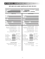
Page 20: ... Modes Approx 5 seconds Use PAL RV Diagnostic Tool for these tests ICEMAKER MODELS Inspect Water Valve and All Connections Yes No Inspect Heat Tape Switch for Proper Operation Yes No SECOND YEAR Date Dealership Address City State Zip Phone Technician Cleaned Burner Assembly Yes No Cleaned Check All Terminals Connections Yes No Cleaned Inspect All Ground Connections Yes No Inspect and Test Door Sea...

Page 21: ......

Page 22: ......

Page 23: ...is wise investment We at Dometic back our products with one of the most comprehensive warranties in the industry Complete the registration card and mail to us or register your Product on line at www edometic com Tape here TIME DATED MATERIAL Please Process Promptly first class postage required Tape here Dometic Processing Center 2320 Industrial Parkway Elkhart IN 46516 ...

Page 24: ...sures you of an invitation to take advantage of an Optional 2 Plus 3 Full Service Contract which allows you to add up to 3 years of additional warranty coverage Return the card within 10 days to ensure your warranty verification factory communication owner confirmation 2 plus 3 service contract Fold here Close with tape Email Address Refrigerator model number serial number Name Address City Stat P...

Reviews: