background image

41

EN

Frigo DC

Disposal

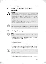
On the positive line (35 mm

2

) (see circuit diagram fig.

f

, page 10, fig.

g

page 10 and supplementary sheet) of the electrical compressor measure the 
power consumption with a current clamp. The measured value should corre-
spond to the table below:

12

Disposal

M

If you wish to scrap the product, ask your local recycling center or specialist 
dealer for details about how to do this in accordance with the applicable dis-
posal regulations.

Outside temperature

High pressure

Compressor power 
consumption at 
maximum speed

Approx. 15 °C

Approx. 7 bar

Approx. 60 A

Approx. 20 °C

Approx. 9 bar

Approx. 70 A

Approx. 25 °C

Approx. 10 bar

Approx. 80 A

Approx. 30 °C

Approx. 12 bar

Approx. 95 A

Approx. 35 °C

Approx. 14 bar

Approx. 105 A

Frigo_DC-I-West.book  Seite 41  Mittwoch, 24. Juni 2020  11:27 11

Summary of Contents for Frigo DC 2500

Page 1: ...ystem Installation Manual 17 Elektrische Transportk hlanlage Montageanleitung 43 Syst me lectrique de refroidissement pour le transport Instructions de montage 70 Elektrisch mobiel koelsysteem Montage...

Page 2: ...right and design law The underlying technical design and the products contained herein may be protected by design patent or be patent pending The trademarks mentioned in this manual belong to Dometic...

Page 3: ...Frigo DC 2 3 4 2 1 1 Frigo DC 2500 2 7 1 3 5 15 4 6 8 9 10 11 12 13 14 2 Frigo_DC I West book Seite 2 Mittwoch 24 Juni 2020 11 27 11...

Page 4: ...3 Frigo DC Frigo DC 3500 2 7 1 3 5 4 6 8 9 10 11 12 13 15 14 3 4 7 5 8 1 2 9 3 6 4 Frigo_DC I West book Seite 3 Mittwoch 24 Juni 2020 11 27 11...

Page 5: ...Frigo DC 4 35 mm 60 mm 170 mm 24 mm 80 mm 5 2 2 2 2 2 2 2 1 6 Frigo_DC I West book Seite 4 Mittwoch 24 Juni 2020 11 27 11...

Page 6: ...5 Frigo DC 80 mm 20 mm 20 mm 377 mm 591 mm 4 5 mm 1 Frigo DC 2500 7 80 mm 20 mm 20 mm 377 mm 840 mm 4 5 mm 1 Frigo DC 3500 8 Frigo_DC I West book Seite 5 Mittwoch 24 Juni 2020 11 27 11...

Page 7: ...Frigo DC 6 9 P 1 2 3 4 76 35 56 3 28 0 Frigo_DC I West book Seite 6 Mittwoch 24 Juni 2020 11 27 11...

Page 8: ...7 Frigo DC 71 mm 29 mm a 60 mm 60 mm 20 mm M4 x 16 3 9 x 9 5 M4 b 1 2 c Frigo_DC I West book Seite 7 Mittwoch 24 Juni 2020 11 27 11...

Page 9: ...Frigo DC 8 A C D E F G B d Frigo_DC I West book Seite 8 Mittwoch 24 Juni 2020 11 27 11...

Page 10: ...9 Frigo DC 13 32 5 16 5 16 1 2 5 16 1 2 1 2 7 8 4 5 3 6 e Frigo_DC I West book Seite 9 Mittwoch 24 Juni 2020 11 27 11...

Page 11: ...Frigo DC 10 f AC INPUT 1 2 3 4 5 STATUS TEMP LIN1 LIN2 1 2 3 4 DC OUTPUT g Frigo_DC I West book Seite 10 Mittwoch 24 Juni 2020 11 27 11...

Page 12: ...11 Frigo DC h 80 mm i Frigo_DC I West book Seite 11 Mittwoch 24 Juni 2020 11 27 11...

Page 13: ...Frigo DC 12 2 1 j 2 3 1 4 k Frigo_DC I West book Seite 12 Mittwoch 24 Juni 2020 11 27 11...

Page 14: ...13 Frigo DC Frigo DC 3500 Frigo DC 2500 l m Frigo_DC I West book Seite 13 Mittwoch 24 Juni 2020 11 27 11...

Page 15: ...Frigo DC 14 A B n 2 3 1 o Frigo_DC I West book Seite 14 Mittwoch 24 Juni 2020 11 27 11...

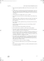
Page 16: ...15 Frigo DC p 3 mm 24 mm 230 V 10 3 1 4 5 9 11 8 2 6 7 q Frigo_DC I West book Seite 15 Mittwoch 24 Juni 2020 11 27 11...
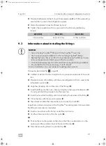
Page 17: ...ing the transport refrigeration system 25 7 1 Prerequisites for the installation 25 7 2 Installation instructions 25 7 3 Checking installation conditions 28 7 4 Installing the DC unit 28 7 5 Installin...

Page 18: ...resulting from mechanical influences and incorrect connection voltage Alterations to the product without express permission from the manufacturer Use for purposes other than those described in the ope...

Page 19: ...rneath the vehicle are not covered The openings and fans on the evaporator in the loading area must not be cov ered during loading Ensure that the insulation installed in the vehicle is in a flawless...

Page 20: ...dchain from the place of origin manufacturer to the customer The transport refrigera tion system can be used in a temperature range between 0 C and 20 C in the refrigerator compartment The transport r...

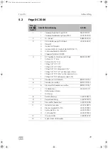
Page 21: ...mperature NOTE You can find additional information on the transport refrigeration system in the operating manual such as the technical description or the controls Item in fig 2 page 2 Qty Description...

Page 22: ...4 12 1 Sign 4445900252 13 1 Evaporator type plate 14 6 6 5 4 4 10 1 Fastening material Oval head screw stainless steel M6 x 20 DIN 7985 Sealing shim stainless steel 7 x 22 Oval head self tapping screw...

Page 23: ...Fitting 5 8 45 5 16 Fitting 5 8 45 connector 5 16 Fitting 7 8 90 1 2 with service valve Fitting 5 8 90 5 16 with service valve Fitting 5 8 90 external thread 5 16 8881400789 5 1 Condensation hose 8881...

Page 24: ...ble Cable set extension Compressor connection cable Evaporator cable set 4441300267 4441300270 4441300269 4441300271 Item in fig 4 page 3 Qty Description Ref no 1 1 Battery charger 80 A 9600000032 2 1...

Page 25: ...125 A Thermal insulation at least k value 0 4 W m2 K DANGER Danger of fatal electric shock Before starting any installation work disconnect the battery and make sure that no voltage can be transferre...

Page 26: ...the parts concerned to ensure the system is kept free of moisture and dust 7 2 2 Instructions on handling cables and hose lines Use ductwork or cable ducts if it is necessary to lay cables through pan...

Page 27: ...Fasten the cable sets with cable binders and hose clips Join the compact plug connections so that snap in points are fixed During the assembly of the watertight plug housing ensure that the rubber sea...

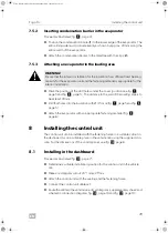
Page 28: ...d please inform workshop manage ment and the vehicle owner 7 4 Installing the DC unit A 7 5 Installing the evaporator 7 5 1 Making through holes in the insulation Mark the position of the drill holes...

Page 29: ...ling the control unit The control unit can be installed with the fastening frame in a suitable cutout in the dashboard or on a suitable place in the vehicle cab using the supplied con sole For the dim...

Page 30: ...7 Make sure that the O ring 1 is sitting on the correct position on the fitting NOTICE Do not exceed the specified tightening torque under any circumstances This is the only way to avoid unintentiona...

Page 31: ...with the mounting pliers E Then check whether the clips are flush and correctly closed F UseeitheraslottedscrewdriverortheFrigoflex mountingplierstodisassemble the fitting and proceed as illustrated I...

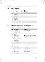
Page 32: ...vaporator unit 3500 A3 Evaporator unit 2500 BAT Battery BL Battery charger only with stationary cooling optional C1 Inverse diode only with stationary cooling optional D2 Pressure transducer F1 Blade...

Page 33: ...vaporator fan M1 X11A 5 pin plug connection X11B 5 pin plug connection X19B DEFA socket Input 220 V only with stationary cooling optional X20B 4 pin plug connection X22A 3 pin plug connection X23A 6 p...

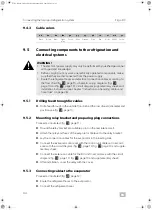
Page 34: ...unit in accordance with the circuit diagram fig f page 10 fig g page 10 and supplementary sheet After installation cover the relay with the cover 9 5 3 Connecting cables to the evaporator Proceed as i...

Page 35: ...o the DC unit Proceed as illustrated fig m page 13 Route the refrigerant hoses under the vehicle to the DC unit Route the extension cable under the vehicle to the DC unit Connect the refrigerant hoses...

Page 36: ...th a fault current protected switch with a nominal current of 30 mA and an earthed splash water protected mains socket If the mains fuse or the fault current switch trips when connecting the sta tiona...

Page 37: ...5 over the cable and attach the socket 1 CAUTION The MiniPlug connection plug is to be fitted so that it is protected from splashing water and mechanical damage The device connector plug must be attac...

Page 38: ...y cable from the battery charger to the vehicle bat tery and connect it in accordance with the circuit diagrams fig g page 10 and supplementary sheet Mount the fuse supports as illustrated fig n page...

Page 39: ...o switch off The compressor of the electrical refrigeration system is operated via the vehicle s on board supply The power consumption of the electrical com pressor is therefore dependent on the opera...

Page 40: ...r the evaporator fan starts after reaching below 15 C Select the L10 parameter and check the current value for the condenser fan The value must be at 100 Select the L11 parameter and check the current...

Page 41: ...scrap the product ask your local recycling center or specialist dealer for details about how to do this in accordance with the applicable dis posal regulations Outside temperature High pressure Compre...

Page 42: ...A Refrigerant R 134a Refrigerant quantity 800 g CO2 equivalent 1 144 t Global warming potential GWP 1430 Refrigerant oil Zerol Ester 68SL Refrigerant oil quantity 100 ml Compressor cylinder capacity 1...

Page 43: ...Standk hlung optional 50 6 Zubeh r 50 7 Montage der Transportk hlanlage 51 7 1 Voraussetzungen f r die Montage 51 7 2 Montagehinweise 51 7 3 Montagebedingungen pr fen 53 7 4 DC Einheit montieren 54 7...

Page 44: ...che Anschlussspannung Ver nderungen am Produkt ohne ausdr ckliche Genehmigung vom Hersteller Verwendung f r andere als die in der Anleitung beschriebenen Zwecke GEFAHR Sicherheitshinweis auf eine Gefa...

Page 45: ...tter unter dem Fahrzeug nicht abgedeckt sind Im Laderaum d rfen die ffnungen bzw L fter am Verdampfer beim Beladen nicht abdeckt werden Stellen Sie sicher dass sich der im Fahrzeug befindliche Isolier...

Page 46: ...m Kunden Die Transportk hlanlage kann in einem Temperaturbereich f r den K hlraum zwi schen 0 C und 20 C eingesetzt werden Die Transportk hlanlage ist nur f r das K ltemittel R 134a geeignet Optional...

Page 47: ...HINWEIS Weitere Informationen zur Transportk hlanlage wie die technische Beschrei bung oder Bedienung finden Sie in der Bedienungsanleitung Pos in Abb 2 Seite 2 Anzahl Bezeichnung Art Nr 1 1 1 Verdamp...

Page 48: ...4445200184 12 1 Hinweisschild 4445900252 13 1 Typenschild Verdampfer 14 6 6 5 4 4 10 1 Befestigungsmaterial Linsenschraube M6 x 20 DIN 7985 Edelstahl Dichtscheibe 7 x 22 Edelstahl Linsenkopf Blechschr...

Page 49: ...ing 5 8 45 5 16 Fitting 5 8 45 Verbinder 5 16 Fitting 7 8 90 1 2 mit Serviceanschluss Fitting 5 8 90 5 16 mit Serviceanschluss Fitting 5 8 90 Au engewinde 5 16 8881400789 5 1 Kondenswasserschlauch 888...

Page 50: ...eite 3 Anzahl Bezeichnung Art Nr 1 1 Batterielader 80 A 9600000032 2 1 Terminalbr cke f r Batterielader 76 5400 0033 3 1 Kabelsatz 4441300273 4 1 MiniPlug 230 V Anschlusskabel 2 5 m A460960 5 1 MiniPl...

Page 51: ...chtigungen der Funktionen f hren Dies kann zum Ausfall von fahrzeugseitigen Komponenten oder sicherheits relevanten Fahrzeugeinrichtungen und als Folge zu Unf llen mit Personen sch den oder Sch den a...

Page 52: ...unmittelbar vor Einbau der betreffenden Teile um das System von Feuchtigkeit und Staub freizuhalten 7 2 2 Hinweise zum Umgang mit Kabeln und Schlauchleitungen Verwenden Sie Leerrohre oder Leitungsdurc...

Page 53: ...e sicher dass nachtr glich verbaute Sicherungsgeh use au erhalb vonSpritzwasserbereichenverbautwerden HaltenSiedabeieinenMindest abstand von 30 mm zu Fl ssigkeitskreisl ufen ein Zwischen den Sicherung...

Page 54: ...rung zwei Bohrungen mit leichter Neigung Durch messer siehe Abb 5 Seite 4 7 5 2 Kondenswasserflies in den Verdampfer einsetzen Gehen Sie vor wie dargestellt Abb 6 Seite 4 Positionieren Sie das Kondens...

Page 55: ...zeugkabine montiert werden Abmessungen des Bedienteils siehe Abb 0 Seite 6 8 1 Montage in der Armaturentafel Gehen Sie vor wie dargestellt Abb a Seite 7 Legen Sie einen geeigneten Einbauort f r das Be...

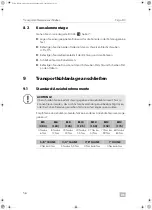
Page 56: ...nschlie en 9 1 Standard Anziehdrehmomente A Empfohlene Anziehdrehmomente falls kein anderes Anziehdrehmoment ange geben ist ACHTUNG berschreiten Sie keinesfalls das angegebene Anziehdrehmoment Nur so...

Page 57: ...ten Sie die angegebenen Anziehdrehmomente Ein zu hohes Anziehdrehmoment besch digt den O Ring Sitz und f hrt zu Undichtig keiten Verwenden Sie beim Anziehen oder L sen eines Anschlusses zwei Schrauben...

Page 58: ...litzschrauben dreher oder die Frigoflex Montagezange und gehen Sie vor wie dargestellt F hren Sie einen Schraubendreher mit flacher Spitze unter den Clip verschluss Hebeln Sie den Clip mit dem Schraub...

Page 59: ...ssepunkt RL1 Relais 12 V 70 A Steuerung Verdampferl fter RL2 Relais 12 V 30 A Steuerung Kompressor Kondensatorl fter RL7 Relais 12 V 200 A Steuerung Kompressor K1 Kompressor M1 Verdampferl fter M2 Kon...

Page 60: ...ng X26A 26 polige Steckverbindung Anschluss Bedienteil X27 Power Terminal X29B 1 polige Steckverbindung Anschluss T rkontaktschalter X32A 3 polige Steckverbindung nur mit Standk hlung optional X32B 3...

Page 61: ...rungskabel f r die DC Einheit nach Schaltplan Abb f Seite 10 Abb g Seite 10 und Beiblatt an Decken Sie das Relais nach der Montage mit der Abdeckung ab 9 5 3 Kabel und Leitungen an Verdampfer anschlie...

Page 62: ...llt Abb m Seite 13 Verlegen Sie die K ltemittelschl uche unter dem Fahrzeug zur DC Einheit Verlegen Sie das Verl ngerungskabel unter dem Fahrzeug zur DC Einheit Schlie en Sie die K ltemittelschl uche...

Page 63: ...zschalter mit 30 mA Nennfehlerstromundeinergeerdeten spritzwas sergesch tzten Netzsteckdose betrieben werden Sollte die Netzsicherung oder der Fehlerstromschalter beim Anschluss der Standk hlung ausl...

Page 64: ...Der Ger teanschlussstecker ist so anzubringen dass die MiniPlug Anschluss leitung ohne Schwierigkeiten eingesteckt werden kann Schlie en Sie schwarze Masseleitung mit Ringkabelschuh niemals am Minuspo...

Page 65: ...m Batterielader Schlie en Sie das rote Kabel an die CN2 Buchse des Batterieladers an Abb o Seite 14 und Schaltpl ne Abb g Seite 10 und Beiblatt Schlie en Sie das rot schwarze Kabel an die CN2 Buchse d...

Page 66: ...ressorderelektrischenK hlanlagewird berdasfahrzeugseitige Bordnetz betrieben Die Stromaufnahme des elektrischen Kompressors ist daher abh ngig von dem jeweiligen Betriebszustand Nach jedem Stillstand...

Page 67: ...en Sie alle Nebenverbraucher des Fahrzeugs aus Schalten Sie das Bedienteil mit der Taste ein Ein Kontrolltest wird durchgef hrt W hlen Sie einen Regelsollwert f r den Laderaum zwischen 0 C und 2 C Dr...

Page 68: ...ck auf der Hochdruckseite und die dazu erwartende Stromaufnahme des elektrischen Kompressors die sich nach der vorgenannten Einstellung ergeben Ausgang f r die Funktionspr fung ist das Ablesen der Dru...

Page 69: ...A K ltemittel R 134a K ltemittelmenge 800 g CO2 quivalent 1 144 t Treibhauspotential GWP 1430 K lte l Zerol Ester 68SL K lte lmenge 100 ml Hubraum Kompressor 18 cm3 Ger uschemission 70 dB A Betriebst...

Page 70: ...6 Accessoires 78 7 Installation du syst me de refroidissement pour le transport 79 7 1 Conditions d installation 79 7 2 Instructions de montage 79 7 3 V rification des conditions de montage 81 7 4 In...

Page 71: ...par le fabricant du v hicule et par les professionnels de l automobile Le fabricant d cline toute responsabilit pour des dommages dans les cas suivants des d fauts de montage ou de raccordement DANGER...

Page 72: ...isez le syst me de refroidissement pour le transport que pour l usage pr vu par le fabricant et n effectuez aucune modification ou transformation du produit Si le syst me de refroidissement pour le tr...

Page 73: ...Ce manuel est destin un personnel d atelier qualifi familiaris avec les direc tives et consignes de s curit observer Le personnel qualifi doit b n ficier d une sp cialisation dans le domaine des quip...

Page 74: ...ns d inspection et de maintenance A I I AVIS Faites fonctionner le syst me de refroidissement pour le transport unique ment lorsque le moteur tourne pour viter de vider la batterie du v hicule Une sou...

Page 75: ...on 7 8 45 1 2 Manchon 5 8 45 5 16 Manchon 5 8 45 connecteur 5 16 Manchon 7 8 90 1 2 avec couplage de service Manchon 5 8 90 5 16 avec couplage de service Manchon 5 8 90 filetage ext 5 16 8881400788 5...

Page 76: ...1 C ble de raccordement du groupe DC Rallonge du jeu de c bles C ble de raccordement du compresseur Jeu de c bles pour vaporateur 4441300267 4441300270 4441300269 4441300271 Position dans fig 3 page...

Page 77: ...s 4442500874 9 1 Cache de relais 4443000379 10 1 Console pour unit de commande 4443000494 11 2 4 4 4 Support pour console Vis t le 3 9 x 9 5 Vis M4 x 16 Rondelles en U M4 4442500875 4445200182 4445200...

Page 78: ...ecteur 230 V c ble de raccorde ment 2 5 m A460960 5 1 Mini connecteur 230 V c ble de raccorde ment 1 5 m A704559 6 1 Mini connecteur 230 V c ble de raccorde ment CEE 5 m A706284 7 1 C ble de rallonge...

Page 79: ...des composants mont s sur le v hicule ou de l qui pement de s curit du v hicule et ainsi des accidents impliquant des bles sures corporelles ou un endommagement du v hicule ATTENTION Seule une entrepr...

Page 80: ...ces concern es pour prot ger le syst me de l humidit et de la poussi re 7 2 2 Instructions pour la manipulation des c bles et flexibles Si des lignes lectriques doivent traverser des cloisons ou autr...

Page 81: ...nce de 300 mm doit tre respect e entre les bo tes fusible et les liquides inflam mables filtre carburant r servoir etc Installez la bo te fusibles aussi pr s que possible de la batterie Ne branchez au...

Page 82: ...de condensation dans l vaporateur Suivez la proc dure illustr e fig 6 page 4 Placez le tissu pour eau de condensation 1 sur le bord inf rieur de l vapo rateur La face sup rieure doit d passer r guli...

Page 83: ...e la console fournie Pour les dimensions du panneau de commande voir fig 0 page 6 8 1 Installation dans le tableau de bord Suivez la proc dure illustr e fig a page 7 D terminez un emplacement de monta...

Page 84: ...stallation de garnitures joint torique A AVIS Ne d passez jamais le couple de serrage indiqu Il s agit de la seule mani re d viter un desserrage inopin des raccords viss s ou un cisaillement sous fort...

Page 85: ...uisez le flexible dans la garniture jusqu ce qu il soit recouvert par le dispositif de fixation de la garniture D Refermez les colliers avec les pinces de montage E V rifiez ensuite que les colliers s...

Page 86: ...5 Compresseur 6 lectrovanne normalement ferm e 7 Soupape de service haute pression 8 Soupape de service basse pression Rep re Description Fonction A1 Unit de commande Commande de l ensemble de l insta...

Page 87: ...ure de la batterie X2B Prise de raccordement 3 p les Raccordement RS 485 X5A Prise de raccordement 2 p les X5B Prise de raccordement 2 p les Capteur de temp rature S1 X6A Prise de raccordement 2 p les...

Page 88: ...nt 3 p les X34B Prise de raccordement 3 p les X35 Prise DEFA 220 V uniquement avec refroidissement auxiliaire en option Z1 Prise de raccordement 1 p le Raccordement de l allumage 15 bk bn bu lbu gn gy...

Page 89: ...elais avec le cache 9 5 3 Raccordement des c bles l vaporateur Suivez la proc dure illustr e fig j page 12 Acheminez les flexibles de r frig rant jusqu l vaporateur Branchez les flexibles de r frig ra...

Page 90: ...en option I ATTENTION Le raccordement du refroidissement auxiliaire au secteur 230 V doit tre effectu uniquement via un interrupteur de protection contre les courants de fuite avec un courant de fuit...

Page 91: ...de batterie et le com mutateur principal sont maintenus en position et prot g s contre les vibrations pendant la conduite afin de pr venir une panne du refroidissement auxiliaire ATTENTION Lors du mon...

Page 92: ...que 30 x 3 2 3 la bague entretoise 4 et l anneau d crou 5 sur le c ble et fixez la prise 1 Attachez le raccord de masse au v hicule avec la vis t le fournie 6 Posez sur la prise de l appareil l tiquet...

Page 93: ...0 V 9 Reliez le c ble de rallonge 230 V et le c ble du connecteur MiniPlug 10 Branchez le c ble de raccordement 230 V du chargeur de batterie fourni 11 dans la prise ENTR E CA du chargeur de batterie...

Page 94: ...onctionne sur la batterie du v hicule La puissance absorb e du compresseur lectrique d pend donc de l tat op rationnel Apr s chaque mise en veille ou arr t du compresseur celui ci attend un certain te...

Page 95: ...e V rifiez si le ventilateur d vaporateur d marre apr s avoir atteint une temp rature inf rieure 15 C S lectionnez le param tre L10 et v rifiez la valeur actuelle pour le ventilateur de condensateur L...

Page 96: ...ez le produit d finitivement hors service informez vous aupr s du centre de recyclage le plus proche ou aupr s de votre revendeur sp cialis sur les prescriptions relatives la r cup ration des d chets...

Page 97: ...bsorb e 110 A R frig rant R 134a Quantit de r frig rant 800 g quivalent CO2 1 144 t Potentiel d effet de serre GWP 1430 Huile de r frig ration Zerol Ester 68SL Quantit d huile de r frig ration 100 ml...

Page 98: ...05 6 Toebehoren 106 7 De transportkoeling installeren 106 7 1 Voorwaarden voor de installatie 106 7 2 Montage instructies 106 7 3 Installatievoorwaarden controleren 109 7 4 De gelijkstroomeenheid inst...

Page 99: ...ge of aansluitfouten beschadiging van het product door mechanische invloeden en verkeerde aansluitspanning GEVAAR Veiligheidsaanwijzing met betrekking tot een gevaarlijke situatie die leidt tot ernsti...

Page 100: ...is beschadigd Zorg ervoor dat de luchtopeningen roosters onder het voertuig niet afge dekt zijn De openingen en ventilators van de verdamper in de laadruimte mogen tijdens het laden niet afgedekt word...

Page 101: ...j handhaaft de koelketen van de plaats van herkomst fabrikant tot de verbruiker De transportkoeling kan wor den gebruikt bij temperaturen tussen 0 C en 20 C in de koelruimte De transportkoeling is all...

Page 102: ...IE Meer informatie over de transportkoeling vindt u in de gebruiksaanwijzing bij voorbeeld de technische beschrijving van de bedieningselementen Nr in afb 2 pagina 2 Aantal Beschrijving Artikelnr 1 1...

Page 103: ...445200184 12 1 Typeplaatje 4445900252 13 1 Typeplaatje verdamper 14 6 6 5 4 4 10 1 Bevestigingsmateriaal Lenskopschroef roestvrij staal M6 x 20 DIN 7985 Afsluitring roestvrij staal 7 x 22 Lenskopschro...

Page 104: ...Fitting 7 8 45 1 2 Fitting 5 8 45 5 16 Fitting 5 8 45 connector 5 16 Fitting 7 8 90 1 2 met serviceklep Fitting 5 8 90 5 16 met serviceklep Fitting 5 8 90 buitendraad 5 16 8881400789 5 1 Condenswaters...

Page 105: ...oomeenheid Verlengkabelset Aansluitkabel compressor Kabelset verdamper 4441300267 4441300270 4441300269 4441300271 Nr in afb 4 pagina 3 Aantal Beschrijving Artikelnr 1 1 Acculader 80 A 9600000032 2 1...

Page 106: ...ens k waarde 0 4 W m2 K GEVAAR Gevaar voor dodelijke elektrische schokken Alvorens met de installatie te beginnen de accu ontkoppelen en controleren of er geen spanning aan de elektrische componenten...

Page 107: ...van de desbetreffende onderdelen om ervoor te zorgen dat het systeem niet wordt blootgesteld aan vocht en stof 7 2 2 Instructies voor de omgang met kabels en slangen Gebruik buizen of kabelgoten indie...

Page 108: ...evestig de kabelsets met kabelbinders en slangklemmen Verbind de compacte stekkerverbindingen zodanig dat de vergrendelpun ten gefixeerd zijn Zorgertijdensdemontagevandewaterdichtestekkerbehuizingvoor...

Page 109: ...met de verantwoordelijke in de werkplaats en met de voertuigeigenaar 7 4 De gelijkstroomeenheid installeren A 7 5 De verdamper installeren 7 5 1 Openingen in de isolatie maken Markeer de positie van...

Page 110: ...onteren Het bedieningspaneel kan met het montageframe in een passende uitsparing in het dashboard of op een andere geschikte plaats in de voertuigcabine worden gemonteerd met behulp van de meegeleverd...

Page 111: ...Standaard aandraaimomenten A Aanbevolen aandraaimomenten mits er geen ander aandraaimoment is aange geven LET OP Overschrijdnooithetaangegevenaandraaimoment Ditisdeenigemanierom onbedoeld losraken van...

Page 112: ...g in de slang en draai hem daarbij iets in tegengestelde richting C Duw de fitting niet recht op de slang LET OP Neem de gespecificeerde aandraaimomenten in acht Een te hoog aan draaimoment kan de O r...

Page 113: ...nde zijde zich aan de opening bevindt en de puntige zijde aan het einde van de clip G Gebruik de montagetang om de clip te openen G 9 4 Aansluitschema s 9 4 1 Stroomschema voor R 134a afb e pagina 9 v...

Page 114: ...V1 Magneetklep Heetgasregeling X2A 3 polige stekkerverbinding Aansluiting accuscheidingsrelais niet aan sluiten X2B 3 polige stekkerverbinding Aansluiting RS 485 niet aansluiten X5A 2 polige stekkerve...

Page 115: ...ige stekkerverbinding X34B 3 polige stekkerverbinding X35 DEFA contactdoos 220 V alleen met stationaire koeling optioneel Z1 1 polige stekkerverbinding Aansluiting ontsteking 15 bk bn bu lbu gn gy og...

Page 116: ...fdekking op het relais aan 9 5 3 Kabels op de verdamper aansluiten Ga te werk zoals afgebeeld afb j pagina 12 Leg de koelmiddelslangen naar de verdamper Sluit de koelmiddelslangen aan Leg de condenswa...

Page 117: ...n op het voertuigchassis 10 De stationaire koeling monteren optioneel I VOORZICHTIG De 230V aansluiting van de stationaire koeling mag uitsluitend via een aardlekschakelaar met een nominale lekstroom...

Page 118: ...der en de hoofdschakelaar beschermd zijn tegen trillingen tijdens rijden om uitval van de stationaire koe ling te voorkomen VOORZICHTIG De MiniPlug aansluitstekker moet zodanig worden aangebracht dat...

Page 119: ...evestig de contactdoos 1 Bevestig de massaverbinding met de meegeleverde zelftappende schroef 6 aan het voertuig Label de apparaatcontactdoos met het bijgeleverde 230V plaatje 7 10 3 De stationaire ko...

Page 120: ...Sluit de 230V verlengkabel aan op de kabel van de MiniPlug aansluitstekker 10 Steek de bijgeleverde 230V aansluitkabel van de acculader 11 in de AC INPUT aansluiting van de acculader Steek de bijgelev...

Page 121: ...ls de motor draait om te voor komen dat de voertuigaccu leegloopt Te lage spanning van de stroom voorziening leidt tot uitschakelen van de koelinstallatie Decompressorvandeelektrischekoelinstallatiewe...

Page 122: ...tief zijn I Meethetstroomverbruikaandepluspoolkabel 35 mm2 zieschakelschema afb f pagina 10 afb g pagina 10 en bijlage van de elektrische com pressor met een stroomtang De gemeten waarde moet overeenk...

Page 123: ...ing optioneel 12 Vg 230 Vw 50 Hz gebruik op het stroomnet Opgenomen vermogen 110 A Koelmiddel R 134a Koelmiddelhoeveelheid 800 g CO2 equivalent 1 144 t Aardopwarmingsvermogen GWP 1430 Koelmiddelolie Z...

Page 124: ...0 0 s YOUR LOCAL DEALER dometic com dealer YOUR LOCAL SUPPORT dometic com contact dometic com 1 01 1 0 4 0 1 1 2 2 1 2 9 0 DOMETIC GROUP AB 3E 0 1 4 4445102703 06 2020 Frigo_DC I West book Seite 124...

Reviews: