


domat UC220
03/2017 Subject to technical changes.
3
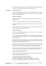
DIP switches
Back of the PCB
BUS END: if ON, the bus is terminated (if last
device on the line)
USR:
not used, reserved for future
applications
INIT:
sets the controller into default state
and sets bus address to 1, baud rate to 9600.
To init, proceed as follows:
- connect the device over RS485 to a PC with
ModComTool config tool
- set INIT to ON
- apply power (use only the connector
without bottom)
- find the controller in the tool (Scan)
- set INIT to OFF
- in the ModComTool tool, open the
controller window
- click the Init button in the tool
- remove and apply power.
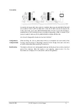
Installation
Units are intended for operating in a normal and chemically non-aggressive
environment. They do not need any servicing or maintenance. Install them in a vertical
position at places where they can be operated easily and measure correct values of
temperature, i.e. in the height of about 150 cm, with no direct sunlight or other heat /
cool source (AHU outlets, refridgerator, electrical appliances). The device consists of
two parts: bottom with screw terminal block and cover containing PCB, display, and the
knob. The bottom part is fixed by 2 or 4 screws to any flat surface or a flush-mounting
box Ø 50 mm. At the back of the bottom there is an aperture for cabling. The bottom
should be installed and cabling connected first, and the upper part inserted after the
construction works have been finished to prevent damage to the unit.
Seal the conduits to avoid influencing the sensor by draught. Use insulating pad when
installing the sensor on cold walls. Avoid sensor exposition to sunlight or other heat
sources.
Opening the
cover
When removing the display part, proceed as follows:
-
press gently the side parts of the unit and pull the right of the display part by
several milimeters
-
pull the left of the display part
-
pull the display part and remove it from the bottom.