


15
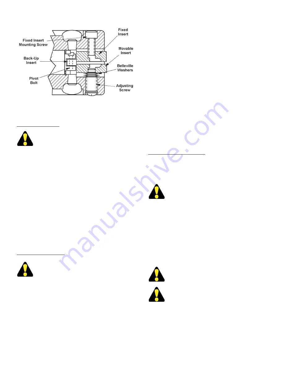
Saw Guide Insert Components.
2.
This applies to both upper and lower saw guides.
Saw Band Removal
Always use extreme care when handling saw
bands. Wear gloves.
1.
Before removing the saw band, set the machine to
the following conditions:
(a)
Hydraulics are on;
(b)
Band drive motor is off;
(c)
Coolant is completely
shut off;
(d)
Saw head is vertical and completely
retracted;
(e)
Position the post at the midrange
height.
2.
Move the
Band Tenson
selector switch to
"release". Then:
(a)
Open the upper bandwheel
door;
(b)
Loosen the band brush bracket screw
and move the brush aside;
(c)
Loosen the saw
guide insert adjustment screws two (2) full turns
counterclockwse
;
(d)
Carefully remove the old,
worn or broken saw band from between the saw
guide inserts and both bandwheels;
(e)
Carefully
work the saw band out from the column guard and
dispose the saw band immediately.
Saw Band Installaton
Always use extreme care when handling saw
bands. DO NOT attempt to change saw bands
whle the band drve motor s runnng.
1.
Carefully follow all
"Saw Band Removal"
procedures.
Then:
(a)
Use the
Flushng Hose
to clean areas
around the saw guides and inserts, plus the drive
and idler bandwheels;
(b)
Wiper with clean rag.
2.
Maneuver the saw band into the column guard.
Then:
(a)
Carefully position the saw band around
the drive and idler bandwheels with the saw band's
back edge resting against each bandwheel's rear
flange;
(b)
Move the
Band Tenson
selector switch
to "tension" to apply just enough tension to hold the
saw band in position, then move the selector to the
center position to "hold".
3.
Slip the saw band between the saw guide inserts
by twisting it 90° using the supplied saw band twist
tool so the blade teeth are facing the front of the
machine and pointing downward. Then:
(a)
Turn
the adjustment screw two (2) full turns
clockwse
to provide correct pressure against the saw band;
(b)
Remove the protective Saw Cap from the saw
band;
(c)
Close the the upper bandwheel door;
(d)
Move the
Band Tenson
selector switch to "tension"
to apply full tension to the saw band.
4.
Turn the
Band
selector switch to "run" and operate
at a very low speed to check for proper band tracking
against the each bandwheel rear flange.
Band Tenson Adjustment
1.
Located on the rear side of the column and accessed
from the left side, band tension is hydraulically
applied and maintained.
DO NOT operate the band drve motor unless
band tenson selector s n the "tenson"
poston.
POST ADJUSTMENT
1.
Post and upper saw guide height is regulated by
the
Post
selector switch on the control panel.
2.
Sawing results will generally be more satisfactory if
the post and upper saw guide are kept as close as
possible to the material being cut. Doing so helps
reduce saw band vibration and contributes to more
accurate sawing.
The post can be lowered only when the saw
head s fully retracted.
When the saw head has been tlted, make sure
the post and saw gude wll clear the materal
and/or the vse jaws.
SAW BAND PREPARATION (Continued....)
Summary of Contents for TF-2525
Page 5: ... MACHINE DIMENSIONS FLOOR PLAN INCHES 03 MILLIMETERS 1 mm ...
Page 6: ... MACHINE DIMENSIONS Continued FRONT VIEW ...
Page 8: ... MACHINE FEATURES FRONT VIEW REAR VIEW ...
Page 9: ... MACHINE FEATURES Continued SIDE VIEW ...
Page 10: ... MACHINE FEATURES Continued HEAD ASSEMBLY ...
Page 25: ...21 LUBRICATION Next 2 Pages ...
Page 27: ...23 LUBRICATION DIAGRAM LOWER HEAD REAR VIEW POWER UNIT REAR VIEW ...


