background image


17 

Product specification 

 
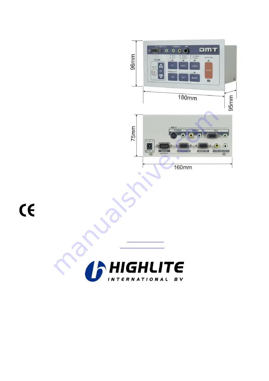
Inputs/ Outputs: 
PC2 VGA input 
PC2 Audio input 
Video 2 video input 
Video 2 audio input 
MIC input 
PC1 VGA input 
PC1 audio input 
VIDEO 1 video input 
VIDEO 1 audio input 
S-VIDEO video input 
S-video audio input 
(YCbCr input optional) 
 
VGA output   


Video output 
Audio output 
 
System requirements: 
Windows 2000/ XP, 128Mb 
30Meg HD, RS232 serial port 


Design and product specifications are subject to change without prior notice. 


Website: 

www.Highlite.nl


Email: 

[email protected]


Summary of Contents for Presenter Control Compact

Page 1: ...PRESENTER CONTROL COMPACT ORDERCODE 100802 ...

Page 2: ... rely on DMT for more excellent lighting products We design and manufacture professional light equipment for the entertainment industry New products are being launched regularly We work hard to keep you our customer satisfied For more information iwant dutchmediatools info You can get some of the best quality best priced products on the market from DMT So next time turn to DMT for more great light...

Page 3: ...atures Overview Backside Installation System set up Software installation Running the set up program Serial port control Requirements for the RS232 code Example 1 Example 2 Infrared remote control Maintenance Troubleshooting Product Specifications Appendix 1 PCC Block diagram Appendix 2 Pin definition of programming cable and Infrared learning cable Appendix 3 ASCII table ...

Page 4: ...o a dimmerpack Do not switch the device on and off in short intervals as this would reduce the system s life Only use device indoor avoid contact with water or other liquids Avoid flames and do not put close to flammable liquids or gases Always disconnect power from the mains when device is not used or before cleaning Only handle the power cord by the plug Never pull out the plug by tugging the po...

Page 5: ...losion crash etc You endanger your own safety and the safety of others Connection with the mains Connect the device to the mains with the power plug Always pay attention that the right color cable is connected to the right place International EU Cable UK Cable US Cable Pin L BROWN RED YELLOW COPPER FASE N BLUE BLACK SILVER NUL YELLOW GREEN GREEN GREEN EARTH Make sure that the device is always conn...

Page 6: ...e button click Built in 2 x 1 VGA matrix switcher Built in 3 x 1 video matrix switching module Built in 5 x 1 audio matrix switching module 6 3mm jack MIC input Built in digital tuning module Built in RS232 interface Power supply 12Vdc Fig 1 Included accessories 2 stereo audio cables 3 5mm jack 1 4m 3 5mm jack 2 stereo audio cables 3 5mm jack 1 4m RCA 1 RS232 cable serial port 1 power adapter 1 IR...

Page 7: ...ressing the button switches the external projector on 10 Video 1 Video 2 selection button Pressing this button enables you to select between Video 1 and Video 2 The LED will light green if video 1 is selected and red if video 2 is selected 11 Projector Off Pressing the button switches the external projector off 12 S video YCbCr selection button This button enables you to select between S Video and...

Page 8: ...evice 19 PC 1 VGA input Connect with VGA Out terminal of the PC 1 20 PC 1 Audio Input Connect with the Audio Out terminal of the Video 1 device 21 12Vdc Input Use the supplied adapter only 22 Projector RS232 Terminal Connect with the RS232 terminal of a projector 23 Projector VGA Output Connect with the VGA in terminal of a projector 24 Monitor VGA Output Connect with the VGA in terminal of a moni...

Page 9: ...7 Installation Remove all packing materials from the Presenter Control Compact Check that all foam and plastic padding is removed Connect all cables Host Terminals and Connection Diagram Fig 4 ...

Page 10: ... turn off the power supply to all equipment as well as the computer Please connect the random communication programming cable to the RS232 port of the computer and the Host Turn on the power supply to the host and the computer Insert the CD ROM into the computers CD drive and follow the instructions Running the setup program Run the setup wizard program The computer will start searching for the Pr...

Page 11: ...ctor and click the icon programming Now the setup program will transmit the right RS232 code to the Host If your projector is not in the list you have to program the control protocol yourself using the projectors information PCC will support Projectors which are controlled by either serial port or remote control Please refer to your projectors operating manual or consult your dealer for the right ...

Page 12: ...o Command etc First select USER DEFINED PROJECTOR Now the window shown in Figure 8 on the next page will appear Fig 8 Click serial Port Control after confirmation Now the communication parameters will be identified in advance Baudrate Data number of bits 7 bits or 8 bits Stop Bit 1 bit Verification Mode none even odd space mark Please look up the projectors parameters carefully in the projectors m...

Page 13: ...ers should be entered in window as shown in Figure 9 Fig 9 PC Control Code Power on 02H 00H 00H 00H 00H 02H Power off 02H 01H 00H 00H 00H 03H Input select RGB 02H 03H 00H 00H 02H 01H 01H 09H Input select DVI analog 02H 03H 00H 00H 02H 01H 02H 0AH Input select DVI digital 02H 03H 00H 00H 02H 01H 1AH 22H Input select video 02H 03H 00H 00H 02H 01H 06H 0EH Input select S video 02H 03H 00H 00H 02H 01H ...

Page 14: ... lower case is insensitive Infrared remote control If it is impossible to obtain the Control Code of a projector but the projector can be controlled by infrared Control please select the Infrared Remote Control button See Figure 10 Fig 10 Please make an Infrared Learn Cable see Appendix 1 page 18 and connect the wire as shown in Figure 11 on the next page ...

Page 15: ...The infrared diode should be connected to pins 9 5 and correspond with Anode and Cathode respectively Please place the Infrared LED before the Infrared receiving window of the projector accurately Attention Please confirm that the power supply of the projector is kept on during the infrared study Before executing a certain function please confirm that the projector is ready to receive infrared sig...

Page 16: ...k press No and start all over again Possible causes for problems during infrared learning mode Check the connections of the learning cable Check if the if the infrared LED is correctly placed before the infrared receiving window of the projector Incorrect sampling of infrared code and the projector s action does not correspond with the command Please let the host learn each function in sequence un...

Page 17: ...he Host Connect the programming cable check if connected properly and click the programming button Now the data will be send to the host The transmission speed shall be shown in the transmission process When programming is completed successfully the PCC will restart automatically A pop up window as shown in Figure 15 will appear Confirm and the setup program will be closed Fig 15 ...

Page 18: ...oubleshooting The indication lamp on the control panel is not illuminated Possible causes 1 No proper connection between the power adapter and the PCC 2 No proper power supply from the power adapter The projector is uncontrollable Possible causes 1 The control code of the projector is not right please restart the setup program 2 The communication cable is not connected to the projector appropriate...

Page 19: ...io input VIDEO 1 video input VIDEO 1 audio input S VIDEO video input S video audio input YCbCr input optional VGA output Video output Audio output System requirements Windows 2000 XP 128Mb 30Meg HD RS232 serial port Design and product specifications are subject to change without prior notice Website www Highlite nl Email service highlite nl ...

Page 20: ...18 Appendix 1 PCC Block Diagram ...

Page 21: ...19 Appendix 2 Pin definition of programming cable and Infrared learning cable Pin definition of programming cable Infrared learning cable ...

Page 22: ...device control 3 13 J 4A 81 B8 ï EF device control 4 14 K 4B 82 B9 ð F0 neg Acknowledge 15 L 4C ƒ 83 º BA ñ F1 synchronous idle 16 M 4D 84 BB ò F2 end transm block 17 N 4E 85 BC ó F3 cancel 18 O 4F 86 BD ô F4 end of medium 19 P 50 87 BE õ F5 substitution 1A Q 51 88 BF ö F6 escape 1B R 52 89 À C0 F7 file separator 1C S 53 Š 8A Á C1 ø F8 group separator 1D T 54 8B Â C2 ù F9 record separator 1E U 55 ...

Page 23: ......

Reviews: