DMP Electronics XT Lite Installation Manual Download Page 9

XTL Installation Guide 

Digital Monitoring Products

5

InstallatIon

Secondary Power Supply

6.1  Standby Battery

The XTL rechargeable battery is used to provide 24 hours of backup battery power when DC power is not 

available.  The battery is intended for backup power only and not to operate the XTL panel on a daily basis.  

If the battery is low, or not plugged into the J1 battery connector, a low battery condition is indicated by the 

XTL panel.
Note:  If removing the XTL panel from service, disconnect the backup battery from the XTL connector.

6.2  Replacement

Use the following steps to replace the XTL standby battery.  DMP recommends replacing the battery every 3 

years under normal use.
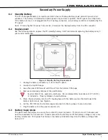
Top PCB Snaps

Bottom PCB Snaps

Battery 

connector

3.7V 

Rechargeable 

Battery

Figure 4: Standby Battery Replacement

1.  Unplug the battery connector (J1) from the XTL panel.
2.  Loosen the top PCB snaps.
3.  Lean the panel PCB forward and lift out from the bottom PCB snaps.
4.  Remove and properly dispose of the used battery.


Caution: Risk of fire, explosion, and burns.  Do not disassemble, heat above 212°F (100°C),  


or incinerate.  Properly dispose of used batteries. 

5.  Place the new battery into the XTL housing base with the battery wires directed toward the 

bottom right corner.  See Figure 4.

6.  Set the XTL PCB into the bottom snaps and press into the top snaps to secure in place.
7.  Plug the battery into the panel connector (J1).

6.3  Battery Supervision

The panel tests the battery once every hour when DC power is present.  This test occurs 15 minutes past 

each hour and lasts for five seconds.  A load is placed on the battery and if the battery voltage is low, a low 

battery is detected.  If DC power has failed, a low battery is detected any time the battery voltage falls 

below 3.7V.

Summary of Contents for XT Lite

Page 1: ...Inst alla tion Guide XT Lite Panel...

Page 2: ...r Connect the equipment into an outlet on a circuit different from that to which the receiver is connected Consult the dealer or an experienced radio TV technician for help Changes or modifications no...

Page 3: ...ndary Power Supply 6 1 Standby Battery 5 6 2 Replacement 5 6 3 Battery Supervision 5 LED Operation 7 1 Backlit Logo 6 Reset Button 8 1 Description 6 Programming Connection 9 1 Programming Connection 6...

Page 4: ...ard Line Security 10 16 2 Remote Disarm 10 16 3 Central Station 10 Household Fire Warning System ANSI UL 985 NFPA 72 Specifications 17 1 Bell Output Definition 10 17 2 Household System 10 17 3 Wireles...

Page 5: ...The XTL panel comes with a SIM card ready for activation with SecureCom Wireless LLC More information is available at www securecomwireless com 1 3 Keypads You can connect up to 4 alphanumeric 9000 S...

Page 6: ...t can be independently armed or disarmed 2 2 Caution Notes Throughout this guide you will see caution notes containing information you need to know when installing the panel These cautions are indicat...

Page 7: ...s dual coverage area selection and sensitivity adjustments 1126C 1126R 1126W PIR Motion Detector Ceiling mount motion detector with panel programmable sensitivity and Disarm Disable functionality 1127...

Page 8: ...e Model 372 500 plug in DC power supply In addition to powering the panel the DC plug in power supply also charges the back up battery The 372 500 must be located within 100 feet of the panel using 22...

Page 9: ...andby Battery Replacement 1 Unplug the battery connector J1 from the XTL panel 2 Loosen the top PCB snaps 3 Lean the panel PCB forward and lift out from the bottom PCB snaps 4 Remove and properly disp...

Page 10: ...ble This provides a quick and easy connection for programming the XTL panel After programming is complete remove the keypad Note The PROG header does not provide a Keypad Data Bus connection On Board...

Page 11: ...firmation During the one minute time period the panel also confirms that programmed keypads are still functioning Wireless Zones 12 1 Description XTL panels provide 28 wireless zones numbered 1 to 28...

Page 12: ...and containing the XTL RU file 3 Start Remote Link and create or open the XTL control panel account that matches the panel to be updated 4 Set the Connection Information Type to Direct with a baud ra...

Page 13: ...ant 14 4 Types Of Service Suitable for Central Station Standard Line Security Suitable for Household Fire and Household Burglary Test weekly 14 5 Bypass Reports The bypass reports must be programmed a...

Page 14: ...TL panel must be programmed to operate steady on burglary alarms and temporal on fire alarms See the XTL Programming Guide 17 2 Household System An alarm sounding device must be installed indoors so t...

Page 15: ...d Programmable 30 sec 240 Sec 30 Seconds At least 30 Seconds 4 2 5 1 Abort Window for Non Fire Zones 3 3 Transmit Delay Required Option Disable by zone or zone type Enabled NT DY EX Zone Enabled 4 2 5...

Page 16: ...ell enabled with a bell cutoff time set to a minimum of 6 minutes to provide a cancel window of 5 minutes or greater This does not apply to manually operated zone types such as Panic and Emergency The...

Page 17: ...ons Revisions to This Document This section explains the changes that were made to this document during this revision This section lists the version section number with heading and a quick summary of...

Page 18: ...ACCESS NETWORKS 2500 North Partnership Boulevard Springfield Missouri 65803 8877 10045 Listings and Approvals FCC Part 15 ID CCKPC0117 Industry Canada ID 5251A PC0117 Underwriters Laboratories UL List...

Reviews: