Digital Monitoring Products
V-4010B-I Indoor/Outdoor HD Video Camera Installation Guide
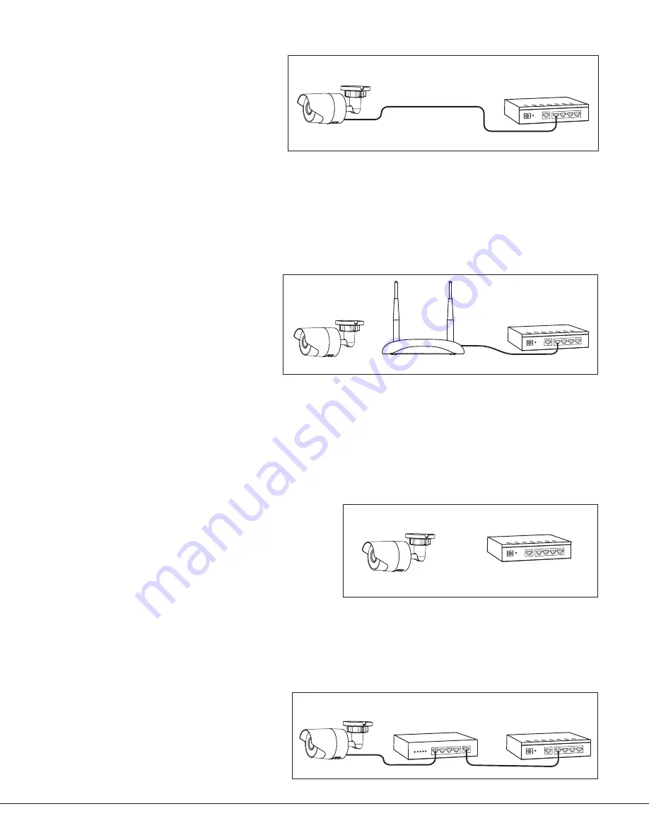
Option #2 Configuration - Wired connection:
1.
IMPORTANT:
Before plugging in power to the
camera, plug an Ethernet cable with an active
internet connection into the Ethernet port.
Recommendation:
It is recommended marking the
Ethernet cable from the customer’s router to the
WAP to help in network troubleshooting. If the end-
user is having network issues after the install, you
can instruct them to remove the marked Ethernet
cable and see if the problem still exists. If it does,
then they can contact their Internet service provider.
2. Once the Ethernet is plugged in, plug in the power adapter to the camera and to the power outlet.
The camera is now ready to be activated through vk.securecomwireless.com.
Option #3 Configuration - Wireless connection using DMP V-IP1006RR WAP
:
For best results, establish communication while the WAP and cameras are no more than 20 ft from each other. After
communication is established, place them in their desired location to ensure that they are still within wireless range
of the WAP. Multiple WAPs can be installed for larger installations.
1. Plug in the power adapter to the camera and
to a power outlet.
2. Press the WPS button on the back of the WAP
for up to 1.5 seconds. The Security LED will
flash to indicate that the WAP is sending a
security key to the wireless camera.
3. Within 1 minute of pressing the WPS button
on the WAP, press and hold the WPS button
for three seconds on the bottom of the
camera. Once the camera and router are fully connected, the WPS LED on the WAP turns on solid.
4. Repeat steps 1-3 for each camera you will be connecting at this site.
Note:
If using DMP WAP, the cameras will pair automatically. If the cameras do not join, your dealer can use the WPS
steps to pair the camera.
Note:
All cameras must be paired with the WAP individually.
The camera is now ready to be activated through vk.securecomwireless.com.
Option #4 Configuration - Wireless connection using a WPS supported router or WAP:
1. Plug in the power adapter to the camera and to a power
outlet.
2. If using a non-DMP WPS-enabled router, refer to the
router’s instruction manual for sending a security key to
the camera.
3. Within 1 minute of sending a security key, press and hold
for three seconds the WPS button on the bottom of the
camera.
4. Repeat steps 1-3 for each camera you will be connecting
at this site.
Note:
All cameras must be paired with the WAP individually.
The camera is now ready to be activated through vk.securecomwireless.com.
Option #5 Configuration - Wired connection using PoE:
Connect the camera to a PoE switch and the PoE
switch to the router.
The camera is now ready to be activated through
vk.securecomwireless.com.
WAN LAN4 LAN3
LAN2 LAN1
RESET
DC 3.3V
Ethernet Cable
Option Two
DHCP Router
WAN LAN4 LAN3
LAN2 LAN1
RESET
DC 3.3V
Ethernet
Cable
DHCP Router
Option Three
Option Four
WAN LAN4 LAN3
LAN2 LAN1
RESET
DC 3.3V
DHCP & WPS
Router
Camera
Camera
Camera
WAN LAN4 LAN3
LAN2 LAN1
RESET
DC 3.3V
PoE Switch
Option Five
Router
Camera
1 2 3
4
PoE
Network
WAN LAN4 LAN3
LAN2 LAN1
RESET
DC 3.3V
Ethernet
Cable
DHCP Router
Option One
Camera
DMP Wireless Access Point
DMP Wireless Access Point
Figure 5: Option #3 - DMP V-IP1006RR WAP Connection
WAN LAN4 LAN3
LAN2 LAN1
RESET
DC 3.3V
Ethernet Cable
Option Two
DHCP Router
WAN LAN4 LAN3
LAN2 LAN1
RESET
DC 3.3V
Ethernet
Cable
DHCP Router
Option Three
Option Four
WAN LAN4 LAN3
LAN2 LAN1
RESET
DC 3.3V
DHCP & WPS
Router
Camera
Camera
Camera
WAN LAN4 LAN3
LAN2 LAN1
RESET
DC 3.3V
PoE Switch
Option Five
Router
Camera
1 2 3
4
PoE
Network
WAN LAN4 LAN3
LAN2 LAN1
RESET
DC 3.3V
Ethernet
Cable
DHCP Router
Option One
Camera
DMP Wireless Access Point
DMP Wireless Access Point
Figure 6: Option #4 - Non-DMP WAP Connection
WAN LAN4 LAN3
LAN2 LAN1
RESET
DC 3.3V
Ethernet Cable
Option Two
DHCP Router
WAN LAN4 LAN3
LAN2 LAN1
RESET
DC 3.3V
Ethernet
Cable
DHCP Router
Option Three
Option Four
WAN LAN4 LAN3
LAN2 LAN1
RESET
DC 3.3V
DHCP & WPS
Router
Camera
Camera
Camera
WAN LAN4 LAN3
LAN2 LAN1
RESET
DC 3.3V
PoE Switch
Option Five
Router
Camera
1 2 3
4
PoE
Network
WAN LAN4 LAN3
LAN2 LAN1
RESET
DC 3.3V
Ethernet
Cable
DHCP Router
Option One
Camera
DMP Wireless Access Point
DMP Wireless Access Point
Figure 7: Option #5 - Wired Connection using PoE
WAN LAN4 LAN3
LAN2 LAN1
RESET
DC 3.3V
Ethernet Cable
Option Two
DHCP Router
WAN LAN4 LAN3
LAN2 LAN1
RESET
DC 3.3V
Ethernet
Cable
DHCP Router
Option Three
Option Four
WAN LAN4 LAN3
LAN2 LAN1
RESET
DC 3.3V
DHCP & WPS
Router
Camera
Camera
Camera
WAN LAN4 LAN3
LAN2 LAN1
RESET
DC 3.3V
PoE Switch
Option Five
Router
Camera
1 2 3
4
PoE
Network
WAN LAN4 LAN3
LAN2 LAN1
RESET
DC 3.3V
Ethernet
Cable
DHCP Router
Option One
Camera
DMP Wireless Access Point
DMP Wireless Access Point
Figure 4: Option #2 - Wired Connection


