Digital Monitoring Products
CellComSL
Series Universal Communicator Installation and Programming Guide
32
Appendix
1
2
3
4
5
6
7
8
9
10
11
12
13
14
15
16
17
18
19
20
21
22
23
24
25
+
+
-
HI
HI
HI
LO
LO
LO
LO
HI
HI
LO
LO
HI
HI
LO
LO
HI
TIP
(BROWN)
RING
(GRAY)
TIP
(GREEN)
RING
(RED)
+
-
BLACK
RED
SYNC
COM
DATA
(USE SA4120XM-1
CABLE)
1 2 3 4 5 6 7 8
OUT 17
+12 A
UX
GND
OUT 18
VISTA 20P ONLY
Ademco
Vista 20P
R
B
J8
S3
J9
RESET
LOAD
S1
S2
J19
J26
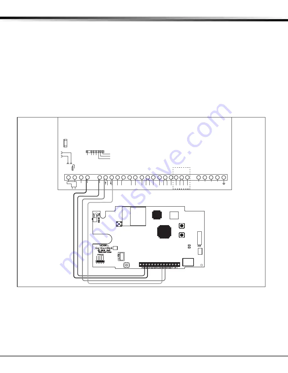
Figure 19: Ademco Vista 20P ECP to CellComSL
18.12 Ademco Vista 20P ECP to CellComSL
18.11 Programming for Ademco Vista 20P ECP to CellComSL
The following steps describe how to configure Ademco/Honeywell
control panels to accept arm and disarm commands
from a
CellComSL using the panel ECP Bus. See Figure 19: Ademco Vista 20P to CellComSL for panel wiring.
1. Program Position * 29: Enter 1.
2. Program Position * 43: Enter Account Number.
3. Program Position * 49: Enter 5.
4. Program Position * 54: Enter 0.
5. Program Position * 55: Enter 1.
6. Program Position * 65: Enter 1.
7. Program Position * 66: Enter 1,1.
8. Program Position * 193: Enter 10
After completing programming in the Ademco/Honeywell control panel, ECP must be enabled in the CellComSL. See
System Options, Keypad Input for additional information.


