2
Assembly
Hi-Cap 40 Grain Cleaner
Step 11 Bolt the electric motor on motor mount on front frame, using four 5/16” x 1” bolts,
eight ¼” flat washers and four 5/16” lock washers and nuts. Slide motor to upper-
most position in the slotted holes. See Photos 20 and 21.
Step 12 Place straight key into motor shaft slot. Next, place 5/8” x 2-
1
/
4
” pulley on the motor
shaft. Align with 14” pulley and tighten setscrews. See Photo 22. At this time, put
a 3/8” Romex connector into the motor junction box. Take loose wire from outlet
box and wire motor as described on wiring diagram on inside cover plate of elec-
tric motor. For 115 Volts, follow low voltage diagram; for 230 Volt, follow high
voltage diagram. Put motor belt (A-55) on the motor pulley and 14” pulley. Adjust
belt tension.
Step 13 Bolt drum bearing mount extension bracket and discharge shield bracket onto the
rear frame end, using two 3/8” x 1-
1
/
4
” bolts, lock washers and nuts. BE SURE
frame end is bolted between bearing mount and shield bracket.
FOR OLD STYLE THREE-PIECE TRASH PAN, SEE SUPPLEMENT PAGE.
FOR CLEANERS WITHOUT TRASH PAN,
ELIMINATE STEPS 14-19, GO DIRECTLY TO STEP 20.
Step 14 Bolt one-half of the collector pan to the rear end panel, using three ¼” x ½” pan
head machine screws, and hex flange lock nuts. See Photo 25. Continue by
bolting the other half of the collector pan to the rear end panel, finish by bolting the
two collector pan halves together at the bottom, using twelve ¼” x ½” pan head
screws, and hex flange lock nuts. See Photo 26.
Step 15 Position four-inch collector pan discharge auger in collector pan with flighting void
directly over the collector pan hole. Bolt front collector pan panel into place with
six ¼” x ½” pan head screws and hex flange lock nuts. See Photo 27.
Step 16 Install front end rear collector pan wooden bearings with six 5/16” x ¾” carriage
bolts, lock washers and hex nuts. See Photo 28.
Step 17 Pull key-wayed end of collector pan auger forward. Place 1” machine bushing to
the auger shaft and hold in position by driving a 3/16” x 1-
1
/
2
” spring pin through the
shaft. Install the 3/16” x 1” woodruff key onto the auger shaft and then position the
8” V-pulley with the hub out approximately 3/16” from the end of the shaft. See
Photos 29 and 30.
Step 18 Bolt the flanged idler pulley to the outside of the front panel using ½” x 3” hex bolt,
½” x ¾” spacer bushing, ½” flat washers. See Photo 31.
Assembly Instructions
(continued)
Summary of Contents for HI-CAP 40
Page 1: ...OWNER S MANUAL HI CAP 40 GRAIN CLEANER PNEG 1146 Date 9 21 06 PNEG 1146...
Page 2: ......
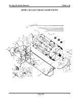
Page 15: ...9 Parts List Hi Cap 40 Grain Cleaner MODEL 40 HI CAP GRAIN CLEANER PARTS...
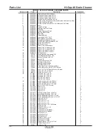
Page 17: ...11 Parts List Hi Cap 40 Grain Cleaner 8 x 8 Auger...
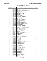
Page 19: ...13 Parts List Hi Cap 40 Grain Cleaner 4 x 15 Fines Auger...
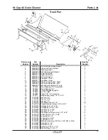
Page 20: ...14 Parts List Hi Cap 40 Grain Cleaner...
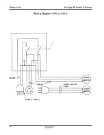
Page 22: ...16 Parts List Hi Cap 40 Grain Cleaner Wiring Diagram 115V or 230 V...


