


DLP-USB245M User Manual
Copyright © DLP Design 2002 Page 9 of 15
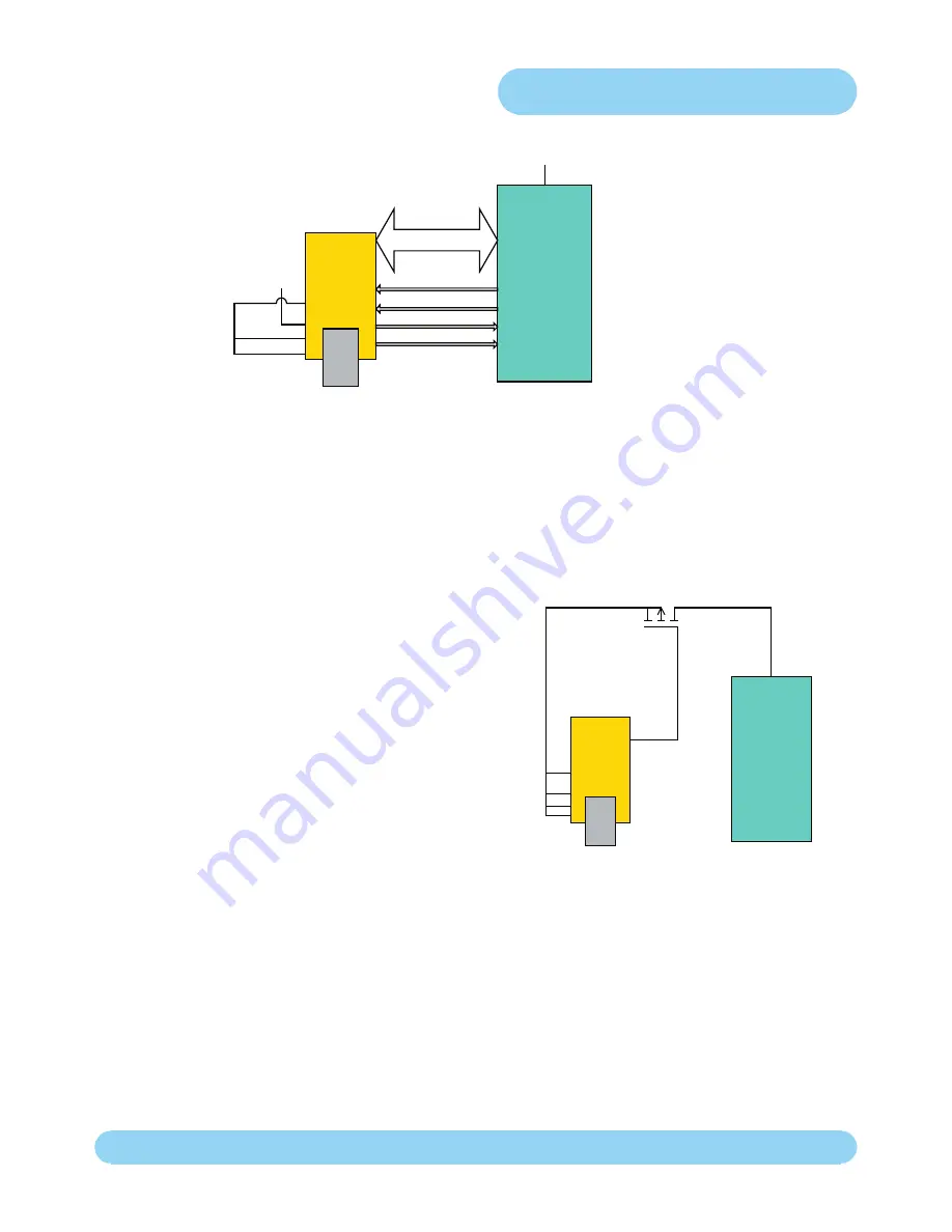
Figure 3
shows how to configure the DLP-USB245M to interface with a 3.3v logic device. In this example, the target
electronics provides the 3.3 volts via the VCCIO line (pin 10) which in turn will cause the FIFO interface IO pins to
drive out at 3.3v level.
Figure 3
Bus Powered Circuit with Power Control
USB Bus powered circuits need to be able to power down
in USB suspend mode in order to meet the <= 500uA total
suspend current requirement (including external logic).
Figure 4
shows how to use a discrete P-Channel Logic Level
MOSFET to control the power to external logic circuits. A
suitable device could be a Fairchild NDT456P or equivalent.
This configuration is suitable for powering external logic where
the normal supply current is <= 100mA and the logic to be
controlled does not generate an appreciable current surge
at power-up. For power switching external logic that takes
over 100mA or generates a current surge on powerup we
recommend that a dedicated power switch i.c with inbuilt “soft-start” is used instead of a MOSFET. A suitable power
switch i.c. for such an application would be a Micrel (www.micrel.com) MIC2025-2BM or equivalent.
Please note the following points in connection with power controlled designs –
a) The logic to be controlled must have it’s own reset circuitry so that it will automatically reset itself when power is re-
applied on coming out of suspend.
b) Set the soft pull-down option bit in the FT232BM EEPROM.
c) For 3.3v power controlled circuits VCCIO must not be powered down with the external circuitry (PWREN# gets it’s
VCC supply from VCCIO).
Figure 4
12
3
10
11
Bus-Powered 5V
System with 3.3 Volt
Logic Interface
3.3V
8
data
RD#
TXE#
RXF#
WR
3.3V
Microcontroller
SLEEP#
Power Controlled by
SLEEP#
12
3
10
11
Microcontroller
P-Channel
Power MOSFET
S
G
D


