


118
seconds): Select the setting option.
Table 8. Work with UPS
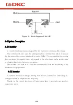
5.2 Display interface
Display
Function
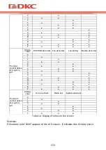
Icon display
Load icon: The approximate load capacity percentage (0-25%, 26-50%, 51-
75% and 76-100%) is indicated by the number of load bar sections
illuminated. When UPS is overloaded, the load icon will flash.
Mute icon: Indicates the audible alarm is disabled/mute.
Press the mute key in the battery mode, the mute icon flash.
Fan icon: Indicates fan working status. When the fan normally runs, the icon
displays rotation; if the fan is not connected or faulty, the icon will flash.
Fault icon: Indicates UPS is in fault mode.
Battery status icon: Indicates the battery capacity of 0-25%, 26-50%, 51-75%,
and 76-100%. When the capacity of battery get low or battery disconnected,
the battery status icon will flash.
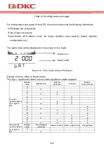
UPS status information
In non-setting mode, it displays UPS output information when UPS
normally runs; Fault code will be told in fault mode.
In setting mode, users could adjust different output voltage, activate ECO
mode, activate CUCF mode, select an ID number and so on by operating
function setting keys and inquiring key.
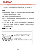
Operation mode
Indicates the power capacity of UPS within 20 seconds after starting up.
Indicates UPS operation mode in 20 seconds, such as STDBY (standby
mode), BYPASS (Bypass mode), LINE (AC mode), BAT (Battery mode),
BATT (Battery Self Test mode), ECO (Economic mode), SHUTDN (Shutdown
mode), CUCF (Constant Voltage and Constant Frequency mode).
LED indicator light functions
Summary of Contents for SMALLR1
Page 2: ......
Page 9: ...7...
Page 10: ...8...
Page 12: ...10 3 3 1 Small Rackmount 3 2 1...
Page 13: ...11 3 3 1 2 3 1 3 4 3 4 1 2 15 3 4 7...
Page 14: ...12 3 5...
Page 17: ...15 4 3 Small Rackmount IGBT VFI IEC EN62040 1 2...
Page 18: ...16 2 4 4 4 4 1 4 4 2...
Page 19: ...17 4 4 3 4 4 4 4 5 3 4 5 1...
Page 20: ...18 4 5 2 4 5 3...
Page 21: ...19 4 6 4 6 1 3 SMALLR1 4 SMALLR2 SMALLR3 1 6 RS232 2 7 SNMP AS400 3 8 RJ45 4 USB 9 5 EPO 10 5...
Page 22: ...20 1 IEC 6 7 2 4 6 2 1 4 1 2 3 5...
Page 24: ...22 4 7 2 SNMP AS400 74 66 40 1 2 SNMP AS400 3 SNMP 5 SNMP card SNMP Ethernet IP SNMP...
Page 27: ...25 5 24 D8 D6 D2 D8 D9 D2 D7 D8 D9 D1 D2 D8 K1 K1 7 DB 9 5 5 1 9...
Page 28: ...26 0 5 0 5 1 1 15 2 2 0 5 2 0 5 2 2...
Page 29: ...27 2 0 5 2 0 5 2 2 0 5 2 8 5 2 0 25 26 50 51 75 76 100...
Page 30: ...28 0 25 26 50 51 75 and 76 100 1 2 ECO CUCF 20 20 STDBY BYPASS LINE BAT BATT ECO SHUTDN CUCF...
Page 31: ...29 ECO LED display 9 5 3 5 3 1 OFF ON ON 0 5 ON 0 5...
Page 32: ...30 5 3 2 OFF 0 5 BPS ON OFF 7 5 4 2 3 8...
Page 33: ...31 5 4 ON ON Line...
Page 34: ...32 bat 4 ECO ECO ECO ECO ECO OFF 10...
Page 35: ...33 5 5 0 5 2 220 50 800 1 0 v1 7 40 220 50...
Page 36: ...34 24 100 11 5 6 2 0 5 2 0 5 2 0 5 2 1 2...
Page 37: ...35 0 5 2 208 220 230 240 9 8 9 9 10 10 2 10 5 50 60...
Page 38: ...36 ON OFF ECO ECO ON ECO OFF ECO EPO EP EPO ON EPO OFF EPO...
Page 39: ...37 6 6 1 1 2 3 6 2...
Page 40: ...38 6 3 1 15 25 C 2 6 3 4 2 5 6 8...
Page 41: ...39 8 2 30 1 2 3 4 5 6 7 7 7 1 7 2...
Page 44: ...42 5 Line 2 2 FAULT bAT 2 2 FAULT 6 byPASS 2 2 7 2 8 FAULT 13...
Page 45: ...43 10 0 1 2 3 4 5 6 7 8 9 A B C D E F...
Page 46: ...44 0 1 2 3 4 5 6 7 8 9 A B C D E F EEPROM Median 0 1 2 3 4 5 6 7...
Page 47: ...45 8 9 A B C D E F 4 0 1 2 3 4 5 6 7 14 2000 7 2 11...
Page 48: ...46 00 14 15 24 25 39 40 44 10 45 49 50 54...
Page 49: ...47 55 59 NTC 60 64 65 69 On 2 3...
Page 50: ...48 15...
Page 53: ...51 12 SMALLR1A5 14 SMALLR2A5...
Page 56: ...54 8 800 250 52 63 service dkc ru www dkc ru...
Page 57: ...55 Lingua italiana...
Page 58: ...56...
Page 101: ...99...
Page 102: ...100 English language...
Page 103: ...101...
Page 138: ...136...
Page 141: ...139 Figure 13 Runtime graph of SMALLR1A10 Figure 14 Runtime graph of SMALLR2A5...
Page 142: ...140 Figure 15 Runtime graph of SMALLR2A10 Figure 16 Runtime graph of SMALLR3A5...
Page 145: ...143...
Page 146: ......
Page 147: ......


