


©2012 DJI Innovations. All Rights Reserved.
2
Warning & Disclaimer
No adjusting or amending is allowed to Z15.
Z15 is specialized for Camera and Lens before it leaves the factory. Please mount your camera to Z15 when
get it. No adjusting or amending is allowed to Z15. Do not modify or add any other component/device (such
as filter, lens hood, etc.) to the camera; make sure to use the original battery; otherwise it may ends up with
worse performance or even internal malfunction.
Z15 can only work with Autopilot system specified by DJI Innovations (
Ace One/ Ace WayPoint/ WooKong
M)
, so as to ensure the highest stability and precision
.Please download the corresponding assistant software
and upgrade the autopilot system MC firmware, otherwise may lead the Z15
work abnormally.
Make sure the Autopilot system operates in the safest manner when the main power battery is connected. We
strongly recommend customers to remove all propellers, use power supply from R/C system or flight pack
battery, and keep children away during gimbal calibration and parameter setup. Please strictly follow these
steps to mount and connect gimbal on your aircraft, as well as to install the assistant software on your
computer.
Please respect the
AMA’s National Model Aircraft Safety Code.
As DJI Innovations has no control over use, setup, final assembly, modification (including use of non-specified
DJI parts i.e. motors, ESCs, propellers, etc.) or misuse, no liability shall be assumed nor accepted for any
resulting damage or injury. By the act of use, setup or assembly, the user accepts all resulting liability. DJI
assumes no liability for damage(s) or injuries incurred directly or indirectly from the use of this product.
DJI and Zenmuse is registered trademark of DJI Innovations Names of product, brand, etc., appearing in this
manual are trademarks or registered trademarks of their respective owner companies. This product and
manual are copyrighted by DJI Innovations with all rights reserved. No part of this product or manual shall be
reproduced in any form without the prior written consent or authorization of DJI Innovations. No patent liability
is assumed with respect to the use of the product or information contained herein.
Note1:
Upgrade WooKong M firmware to V5.08 or above, ACE ONE firmware to V4.02 or above, or ACE
WayPoint
firmware
to V4.02 or above.
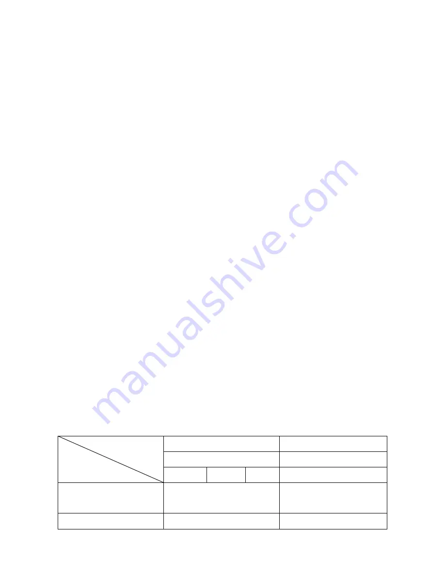
Note2:
Specified
Camera and Lens Type list for Z15-N and Z15-G
.
(Items in
gray italics
font are not yet supported at present
.
)
Z15 Type
Camera Type
Lens Type
Z15-N
Z15-G
SONY
Panasonic
NEX-5N
NEX-7
NEX-5R
GH2
Supported
E 16mm f/2.8(SEL16F28)
Lumix G14 mm/F2.5
Lumix G20 mm/F1.7
Not yet supported
Sonnar T*E 24mm F1.8 ZA
Lumix G 1:2.5 / 14 ASPH
Note3:
All diagrams in the manual are for
SONY NEX-5N
with SEL16F28 unless stated
, since different
camera or lens should use special component
.


