background image

Field of View GeoSnap PPK Manual                                                                                                                         18 

OFFSETS 

Camera to Antenna Offsets


Description 


Type in the X, Y, and Z offsets from the camera to the 
antenna. More information on how to do this correctly is 
below. 


This diagram show how the X, Y, and Z axis aligned to an airframe. It also shows that an offset may be positive or 
negative depending on where the antenna is mounted relative to the camera.  


Using this diagram as a guide, Field of View has already calculated offsets from the antenna to the skyports of the 
M210 when using the GeoSnap PPK with M210 integration kit.  
 
Bottom-center of SKYPORT 

II

-to-antenna L1 phase center offset: 

X offset: -0.034 meters 
Y offset: -0.127 meters 
Z offset: 0.250 meters 
 
Bottom-center of SKYPORT 

I

-to-antenna L1 phase center offset: 

X offset: 0.123 meters 
Y offset: -0.127 meters 
Z offset: 0.250 meters 
 
Note: The final offset values will be unique to your setup based on the specific camera and lens being used. 
Remember offset values are the X, Y, & Z distances from the focal point of the camera to the Phase center of the 
antenna.  The values given above are a starting point that can be referenced for your specific setup.  


Summary of Contents for Matrice M210

Page 1: ...d is meant to be referenced in conjunction with the GeoSnap PPK Manual https fieldofviewllc com downloads If something is not mentioned in this guide then it is most likely discussed in the manual If...

Page 2: ...tallation 3 What s in the Box 3 Installation Procedure 6 System operation 16 Powering the GeoSnap PPK System 16 Battery Information 16 Checking Battery Voltage 16 Battery Charging 16 Purchasing Additi...

Page 3: ...ON WHAT S IN THE BOX GeoSnap PPK and antenna installed on the DJI M210 mount Lower mount bracket for M210 Survey pole mount bracket 16 GB microSD card and microSD card adapter the microSD card will be...

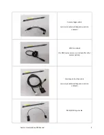
Page 4: ...mera trigger cable version provided will depend on version ordered Hotshoe module for DSLR style cameras not included for other camera options GeoSnap to hotshoe cable version provided will depend on...

Page 5: ...Test plug use this if you want record events without a camera connected Cable routing clips 4 Ziptie 1 Li Po batteries 2 batteries total included DC 4S charger voltage checker AC charging cable inclu...

Page 6: ...using a MicaSense camera you can skip steps 2 3 6 7 8 and 9 If you are using a MicaSense camera please reference the integration guide specific to your camera found at www fieldofviewllc com geosnap p...

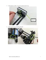
Page 7: ...Field of View GeoSnap PPK Manual 7 2 Install the Micasense DLS 2 on the mount provided by Field of View 3 Install the DLS2 mount on the GeoSnap PPK plate DSL2 cable connector...

Page 8: ...Field of View GeoSnap PPK Manual 8 4 Secure the GeoSnap PPK lower mounting bracket using the 4 screws and included hex key to the top of the drone...

Page 9: ...bracket You must first insert the tab of the GeoSnap PPK into the front receptacle on the lower mounting bracket Then press down and turn the two quarter turn studs clockwise until a click is felt to...

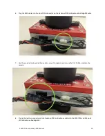
Page 10: ...the GeoSnap PPK to MicaSense RedEdge MX cable 7 Use the provided ziptie and adhesive ziptie mount to organize and secure the DLS 2 ribbon cable to the camera 8 Plug in the last two connectors of the...

Page 11: ...Field of View GeoSnap PPK Manual 11...

Page 12: ...Field of View GeoSnap PPK Manual 12 9 Install the Micasense RedEdge MX in the M210 Skyport as shown the cable lengths are optimized for use in gimbal slot II...

Page 13: ...e location shown and route the DLS 2 ribbon cable through it 11 Next route the GeoSnap PPK to Micasense cable through the same cable clip and use zipties to secure the two cables just below and just a...

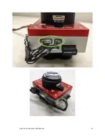
Page 14: ...Field of View GeoSnap PPK Manual 14 12 Plug the DLS 2 ribbon cable into the DLS 2 and the GeoSnap PPK to Micasense RedEdge MX cable into the 6 pin connector from the side of the GeoSnap PPK...

Page 15: ...Field of View GeoSnap PPK Manual 15 13 When you re ready to fly plug in the red battery power connector on the GeoSnap PPK...

Page 16: ...er voltage checker you can even do this while the battery is powering the GeoSnap PPK A full battery has a total voltage of 12 4V 12 6V The battery is practically depleted once has reached 10V A fully...

Page 17: ...ectly via the links below Battery https hobbyking com en_us turnigy 9xr safety protected 2200mah 3s 1 5c transmitter pack html DC 4S charger voltage checker https hobbyking com en_us hobbykingr dc 4s...

Page 18: ...the antenna to the skyports of the M210 when using the GeoSnap PPK with M210 integration kit Bottom center of SKYPORT II to antenna L1 phase center offset X offset 0 034 meters Y offset 0 127 meters Z...

Page 19: ...nting Style Quarter turn quick release Battery included 3 cell 2 2 Ah Li Po Battery life 2 6 hours 1 Includes antenna control module hotshoe module M210 mounting hardware battery and cabling 2 Depende...

Page 20: ...Field of View GeoSnap PPK Manual 20 All dimensions are in millimeters...

Reviews: