background image


CARE AND MAINTENANCE - MODEL ZTR 2301


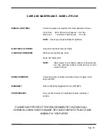
Manual Clutch:  No Adjustment


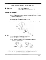
1.  Place cut height lever in lowest cut position.


2.  Loosen belt keepers on each side of engine pulley.


3.  Remove deck drive belt from engine pulley.


4.  Using a slight upward twisting motion, remove link from engagement handle.


5.   Turn handle fully to the left until handle clears stop on mower deck pan. Lift and 

remove handle through hole in lower body.


6.   Remove pin and washer from one end of deck support shaft. Note location of remaining 

shim washers used between chassis and mower deck pan arms. Slide shaft from 

chassis and mower deck. (Refer to illustration below)


7.   Remove pin and washer from each deck adjustment rod. Carefully push each link 

toward the inside of the mower chassis. At this point, deck will drop down.


8.   Carefully raise and support front of chassis. Slide mower deck to either side for 

removal. (Reverse procedure to reinstall deck assembly)


•"•*;•


BELT TENSION:


DECK REMOVAL:


Page 22


Summary of Contents for ZTR 2301

Page 1: ......

Page 2: ...ator s manual carefully and become completely familiar with the controls The information in this operator s manual applies to your Dixon ZTR Model ZTR 2301 Mowers Your Dixon dealer will gladly provide...

Page 3: ...PECIFICATIONS Pages 8 SEAT ADJUSTMENT Page 9 CONTROLS Pages 10 13 OPERATION INSTRUCTIONS Pages 14 19 CARE AND MAINTENANCE Pages 20 26 STANDARD SERVICE PARTS LIST Page 27 TROUBLESHOOTING Pages 28 30 DI...

Page 4: ...RIDING LAWNMOWERS IF IMPROPERLY OPERATED CAN CAUSE SERIOUS INJURY OR DEATH The most common causes of injury to the operator or bystander SAFETY BLADE CONTACT RUN OVER TIP OVER RUN OVER Page 1...

Page 5: ...imminently hazardous situation which if not avoided will result in death or serious injury Warning indicates a potentially hazardous situation which if not avoided could result in death or serious inj...

Page 6: ...hile backing Be aware of the mower discharge direction and do not point it at anyone Do not operate the mower without either the entire grass catcher or the deflector in place Slow down before turning...

Page 7: ...ttachments These can change the stability of the mower Keep all movement on the slopes slow and gradual Do not make sudden changes in speed or direction Avoid starting or stopping on a slope If tires...

Page 8: ...t of the mowing area and under the watchful care of another responsible adult Be alert and turn mower off if a child enters the area Before and during backing look behind and DOWN for small children N...

Page 9: ...ect the equipment if you strike an object Repair if necessary before restarting Never make adjustments or repairs with the engine running Grass catcher components are subject to wear damage and deteri...

Page 10: ...negligence accidents or alteration The use of parts or components other than those supplied by Dixon Industries Inc VOIDS ALL WARRANTY 6 The following items are not covered by this warranty policy a P...

Page 11: ...on mechanical drive 14HP Kohler Command 4 Cycle Single Cylinder Overhead Valve Air Cooled Pressure Lubricated With Oil Filter Vertical Shaft Aluminum Head and Block with Cast Iron Cylinder Liner Elect...

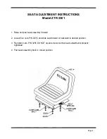
Page 12: ...push seat assembly forward 2 Loosen five nuts P N 3205 and slide seat forward or backward to desired position 3 Re tighten nuts P N 3205 DO NOT operate mower without seat adjustments properly tighten...

Page 13: ...CONTROLS Page 10...

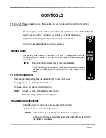
Page 14: ...n motion NOTE Engine cannot be started unless the brake is applied Do not leave engine running for extended periods of time without the parking brake engaged Damage to the drive system could result TO...

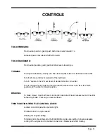
Page 15: ...ion to neutral To turn on mower s own axis zero turning radius stop and move one lever to reverse position and the other to forward position BRAKING To brake mower move both levers in direction opposi...

Page 16: ...utting height Seven positions of adjustment Move lever in and forward to lower Move lever in and back to raise NOTE Always use high position for transport CIRCUIT BREAKER Located on control panel to o...

Page 17: ...functions During initial operation learning to drive set throttle at slow speed Sound judgement by the owner will prevent accidents BEFORE OPERATING MOWER 1 Read engine manufacturer s operating and m...

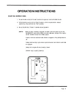
Page 18: ...n On position engine should not turn over or attempt to start when key switch is moved to the start position b In a SAFE AREA away from bystanders start the engine place throttle setting at maximum or...

Page 19: ...le from Choke to desired speed position NOTE While mowing blade s engaged throttle control should be set to the MAXIMUM or wide open setting to insure adequate cooling of the engine and to maintain mo...

Page 20: ...y on first cuttings or if the lawn is heavily fertilized 4 Do Not Attempt To Cut Grass When It Is Wet Mulching performance will be very poor under wet grass conditions 5 Maintain Sharp Blade s Through...

Page 21: ...5 Use only the correct blade s Some grass catching attachments require a high lift blade See your dealer for advice on the type of blade s needed for your mower 6 Maintain Sharp Blade s Throughout The...

Page 22: ...th each pass Some applications may require a second cutting 4 Keep The Underside Of The Mower Deck Clean Frequent removal of dried grass and dirt will allow the clippings to discharge correctly 5 Main...

Page 23: ...40 hours of use 1 Drive chain 2 Drive system belts and controls 3 Mower deck belts 4 Tire pressures 5 Tightness of all nuts and bolts 6 Battery fluid level 7 Engine oil Before performing any maintenan...

Page 24: ...ade position prior to removal 1 Safely raise front of mower 2 Hold or block blade from turning Wear heavy thick gloves when holding onto cutter blade avoid the sharp edge of the blade NOTE Be sure bla...

Page 25: ...ve handle through hole in lower body 6 Remove pin and washer from one end of deck support shaft Note location of remaining shim washers used between chassis and mower deck pan arms Slide shaft from ch...

Page 26: ...SERVICE INTERVALS RECOMMENDED GREASE Number of grease zerks used 4 1 each front wheel caster and each front wheel hub Every 50 hours of operation Name brand wheel bearing or multi purpose grease Lubri...

Page 27: ...the oil 3 Push the valve body in and twist to clear the detent notch 4 Pulling the valve body outward will start the flow of oil NOTE Refer to engine manufacturers recommendations for frequency of oi...

Page 28: ...chain tension 3 Tightness of all controls and linkages pertaining to the drive levers 4 Lubrication of both primary and final drive chains The use of a high quality chain lubricant is highly recommend...

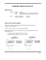
Page 29: ...me at rear of engine it will begin with DM Refer to Warranty Registration Form P N 8871 See your Dixon dealer for replacement parts warranty or service PLEASE HELP PROTECT THE ENVIRONMENT BY AVOIDING...

Page 30: ...lease refer to Kohler Engine Operators Manual for correct service intervals for engine oil changes and air filter maintenance Protect your engine investment use only original equipment filters Model Z...

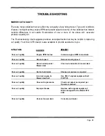
Page 31: ...ailable to provide assistance to you Poor cut quality Engine RPM too low Increase engine RPM to maximum Poor cut quality Ground speed Reduce mowing speed Poor cut quality Grass buildup under Clean out...

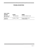
Page 32: ...Mower pulls to one side or the other Drive adjustment Consult your dealer for repair DRIVE SYSTEM SITUATION CAUSES REMEDY Poor driving performance Operation of mower Review operators section of owners...

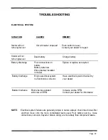
Page 33: ...ning correctly your dealer Battery discharge Engine being operated Increase engine RPM at too low an RPM Contact your dealer for information NOTE Electrical system failures are generally simple in nat...

Page 34: ......

Page 35: ......

Page 36: ......

Page 37: ......

Page 38: ......

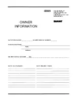
Page 39: ...____ PURCHASED FROM Name Address MOWER SERIAL NUMBER ___DM ______________________________________________ DATE ENGINE TUNED DIXON INDUSTRIES INC A BLOUNT COMPANY AIRPORT INDUSTRIAL PARK PO BOX 1569 CO...

Page 40: ...NOTES...

Page 41: ...NOTES...

Page 42: ...BLOUNT COMPANY AIRPORT INDUSTRIAL PARK PO BOX 1569 COFFEYVILLE KS 67337 0945 316251 2000 FAX 316 251 4117 Part No 8874 September 1995 WARNING The Engine Exhaust from this product contains chemicals kn...

Reviews: