DIXIE GRINDERS 1666D Manual Download Page 24


12.5°

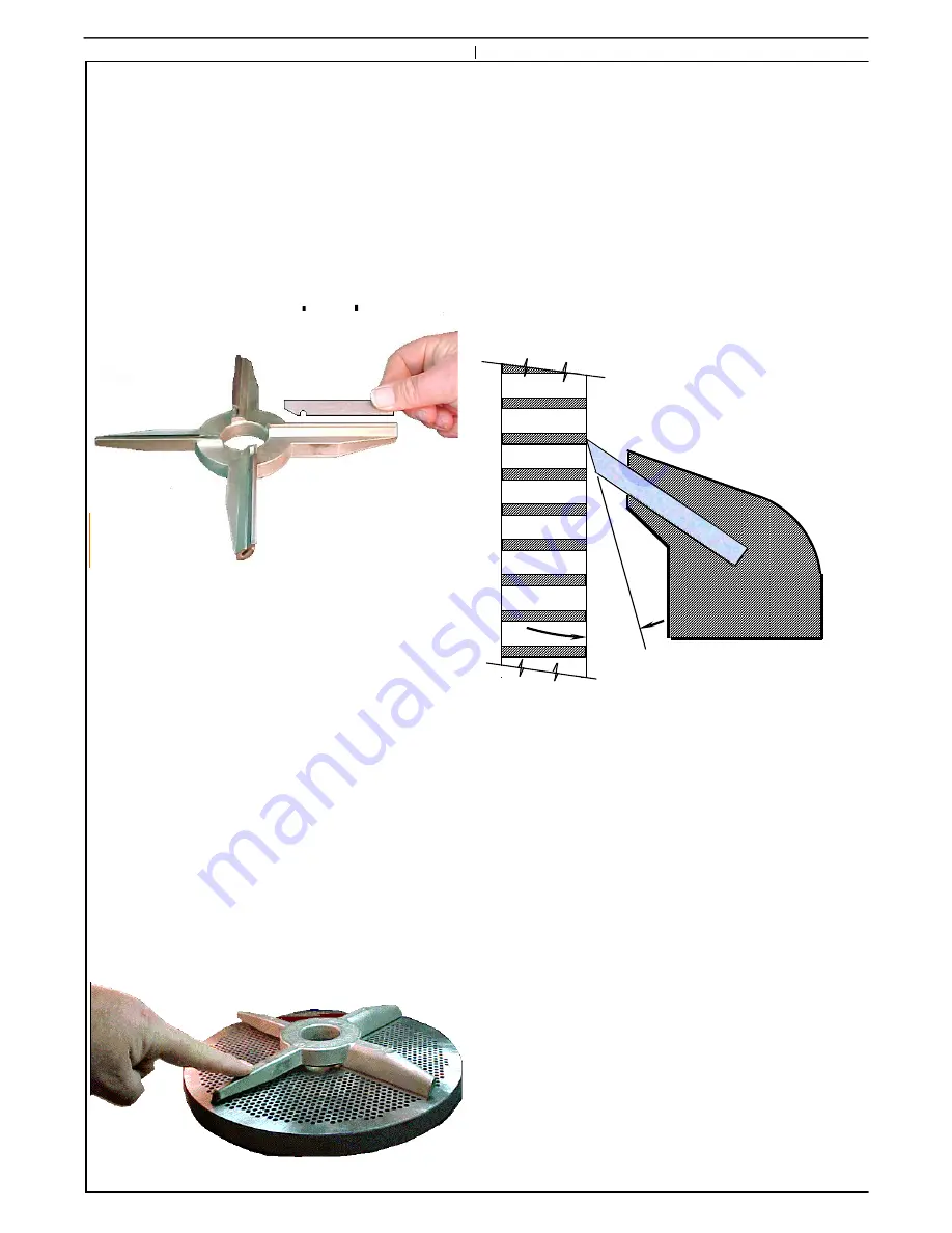
Line the notch of the insert up with the pin in 
the bottom of the slot of the knifeholder.  If 
necessary tap the insert into position with a 
soft mallet, a soft rubber hammer, or a piece 
of pine.   The inserts should fit snugly in the 
slots, but they should not have to be beat in.  
It may be necessary to open the slots slightly 
if they are too tight.  Use a small flat file, or a 
cut-off wheel.  Tap on the face of the 
knifeholder if they are too loose.   

The combination of the insert slot angle and 
the angle that the inserts are ground provide 
that only the leading edge of the knife insert  
contacts the plate.  This slight amount of 
clearance allows the insert to seat within a 
few revolutions of the grinder being turned 
on.  The amount of material removed from 
the leading edge of the insert is not 
measurable, but it is advised that the first 
product that comes out of any meat grinder 
on start up is discarded.  

TAP HERE IF 

LOOSE

.

When the inserts have been properly 
installed turn the knifeholder over and check 
it for flatness.  Use a properly sharpened 
plate, or other known "true flat" surface.  If 
the knifeholder rocks, check to make sure all 
the blades have been properly seated.   Check 
the bottom of the slots for obstructions.  
Make sure that the slot of the insert is lined 
up with the pin in the bottom of the slot.  

A slight rock is permissible, a feeler gauge of 
.005 should not fit under the knife insert that 
is not touching the plate.   

If  inserts are not properly installed,  
excessive clearance will result.  

Excessive clearance will keep the grinder unit 
from functioning properly, and in many cases 
it will not grind.  

We recommend that maintenance, or a 
responsible person is entrusted with the 
function of changing inserts and sharpening 
the grinder plates.   The success of your 
operation depends on it.

If you do not have the equipment to sharpen 
your plates, or you do not know if they are 
being sharpened properly, send them to Dixie 
Grinders Inc. (attention Service Department) 
and we will examine your plate, sharpen it 
properly, and return it to you promptly.  

24

Summary of Contents for 1666D

Page 1: ...45 0586 256 582 0477 FAX 256 582 0478 MODEL 1666D GRINDER UNIT SAFETY INSTALLATION OPERATION MAINTENANCE THIS MANUAL MUST BE READ TO OR BY EACH PERSON BEFORE THAT PERSON OR DEPARTMENT UNCRATES OPERATE...

Page 2: ...PERSONAL INJURY HOPPER GUARD LISTED BELOW IS THE DEFINITION OF THE HAZARD LEVEL USED ON THE SAFETY STICKERS TYPICAL DIXIE GRINDER FRAME MOTOR COVER PANELS SERIAL NUMBER HOPPER RING BELT GUARD HEAD GEA...

Page 3: ...r sidemount frame Standard safety equipment includes a belt guard a hopper guard and a plate guard If a transition funnel is used the plate guard is not required It is important that your application...

Page 4: ...ROVIDED TO RESTRICT ACCESS TO THE ROTATING FEEDSCREW THE PLATE GUARD IS PROVIDED TO RESTRICT ACCESS TO THE PLATE THE KNIFEHOLDER AND THE FRONT END OF THE FEEDSCREW THE BELT GUARD IS PROVIDED TO RESTRI...

Page 5: ...climb on it or use it as a platform Remember to Work Safely THE GRINDER HAS ARRIVED LIFT EQUIPMENT REQUIRED We recommend using a 8 000 pound or greater capacity fork lift with 60 or longer forks Do n...

Page 6: ...be given a lock and key and trained in proper procedures for LOCK OUT TAG OUT Please consult with your Safety Engineer your Electrical Engineer and O S H A for all regulations related to the controls...

Page 7: ...embly to remove the ring The Ratchet Assembly is shown in the locked position for grinder operation To use the Ratchet Assembly with the Power Locked out support the handle with one hand and slide the...

Page 8: ...eville springs 2 each Some pins have a spacer collar behind the Belleville springs if this collar is used remove it also 8 Step 4 KNIFEHOLDER REMOVAL Remove the knifeholder from the face of the grinde...

Page 9: ...he feedscrew in while pulling the pin out Wash out the pin hole after removing the pin in preperation of using the FSP2006 Feedscrew Puller 9 Step 7 REMOVE THE CENTERING PIN Do not loose the pin key w...

Page 10: ...ew removed from the grinder unit it can now be wired Dixie Grinders Inc does not supply motor controls disconnects or stop start stations Please consult your Electrical Engineer your Safety Engineer O...

Page 11: ...large quantities of hot water We strongly recommend drying the unit and applying a liberal amount of mineral oil to all tin plated surfaces If the machine is not going to be used for an extended perio...

Page 12: ...8 Item 2 Add or subtract washers to obtain the 3 4 head space dimension Note In the illustration the Thrust Screw is shown mounted in the hole in the mainshaft If the threads in the main shaft fail or...

Page 13: ...Install the 2935 Pin with the 2936 Pin Key installed into the feedscrew Do not beat the pin into position reposition the key and try again Beating the pin into position will insure that you will never...

Page 14: ...sed height of the two springs is over 1 4 as shown above This is how they are to be installed touching at the center a gap at the outside One spring facing in one facing out Step 5 Install the 2938 sp...

Page 15: ...shear the pins that locate the knife inserts Use a soft mallet a block of soft wood or soft plastic to tap the inserts in place Do not use a steel faced hammer Check the knifeholder for flatness after...

Page 16: ...ng slide into the grinder easily something is wrong 16 Step 8 Install bushing in plate Lubricate the inside of the bushing with an edible lubricatant If you don t know which one to use contact your qu...

Page 17: ...8 turn Return ratchet lever and pawl to the lock position Step 11 Install Ring The grinder ring is heavy Use the RL2000 ring lift if you have one or get help to install the ring Once started on the th...

Page 18: ...S GRINDER RING The grinder ring needs little maintenance other than thread inspection The center support should contact the slip in bushing at the same time that it contacts the plate If there is any...

Page 19: ...d be placed directly over the center of the table We do not recommend sharpening the plates when they are placed out on the table not directly over the center of the table If you have a Pieco or Van N...

Page 20: ...nd feeler guages is the best test for flatness 20 If your plates are turning blue the operators are running the grinder empty The blue color indicates temperatures up to 600 This is above the draw tem...

Page 21: ...a thud Notice the tramp metal stuck in one of the holes The tramp metal must be removed Note the gouges that extend from hole to hole These gouges must be ground out The sharpened grinder plate shoul...

Page 22: ...l conditions the pin usually lasts about three months or three bushings If some roughness is noticed this can be smoothed out with an external grinder or very fine sand paper in a lathe A rough surfac...

Page 23: ...ockwise at the tips Inspect the arms where they are connected to the hub of the knife if there are any signs of cracking throw the knife away immediately Examine the knife inserts The edge of the inse...

Page 24: ...hen the inserts have been properly installed turn the knifeholder over and check it for flatness Use a properly sharpened plate or other known true flat surface If the knifeholder rocks check to make...

Page 25: ...s should have a square corner When they become rounded the head should be rebuilt Bore flute wear can be measured with our head guage When new the bore gauge fits tight The wear limit depends on your...

Page 26: ...side diameter of the pressure flights are rounded They should have a square edge The front of the pressure flight should be flat The outside diameter through the head section is rounded and undersized...

Page 27: ...e flighting we machine the old flighting off right down to the shaft The flighting is replaced with new 1045 bar Examine the drive spline The main shaft does not engage 100 of the drive spline therefo...

Page 28: ...notice that the flighting is thicker When new or rebuilt the corners are square Notice the nice filet welds attaching the flighting to the shaft Sharp cupping is needed to aggressively grasp the prod...

Page 29: ...per at the bottom should have a square corner When this edge becomes rolled over the feedscrew has difficulty feeding the head correctly In time the excluder seal will wear a ridge in the back flange...

Reviews: