2
IMMEDIATE HAZARDS
WHICH WILL RESULT IN
SEVERE PERSONAL INJURY
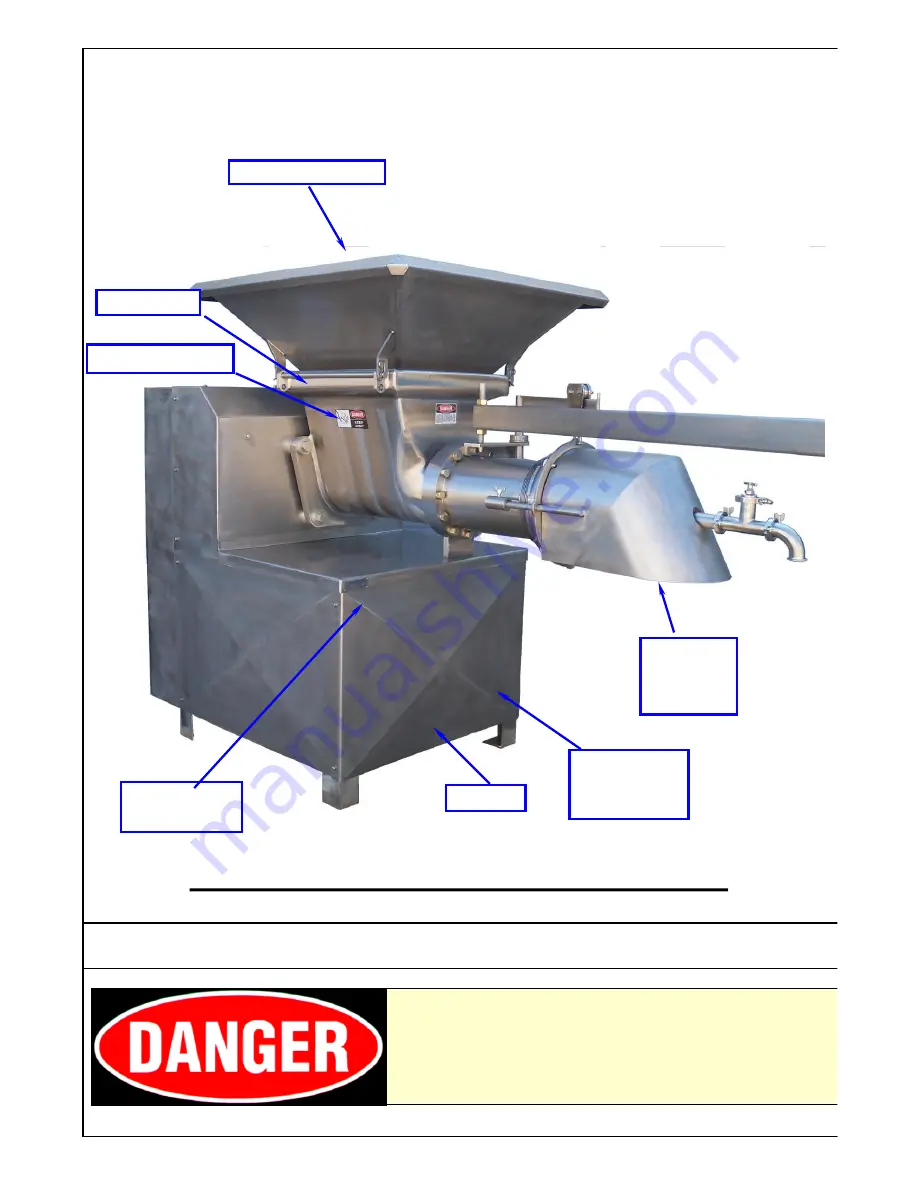
HOPPER GUARD
LISTED BELOW IS THE DEFINITION OF THE HAZARD
LEVEL USED ON THE SAFETY STICKERS.
TYPICAL DIXIE 16-10 GRINDER UNIT
FRAME
MOTOR
COVER
PANELS
SERIAL
NUMBER
HOPPER
SAFETY TAG
ORIFICE
PLATE
GUARD


