background image

- 5 -

3.1.2  

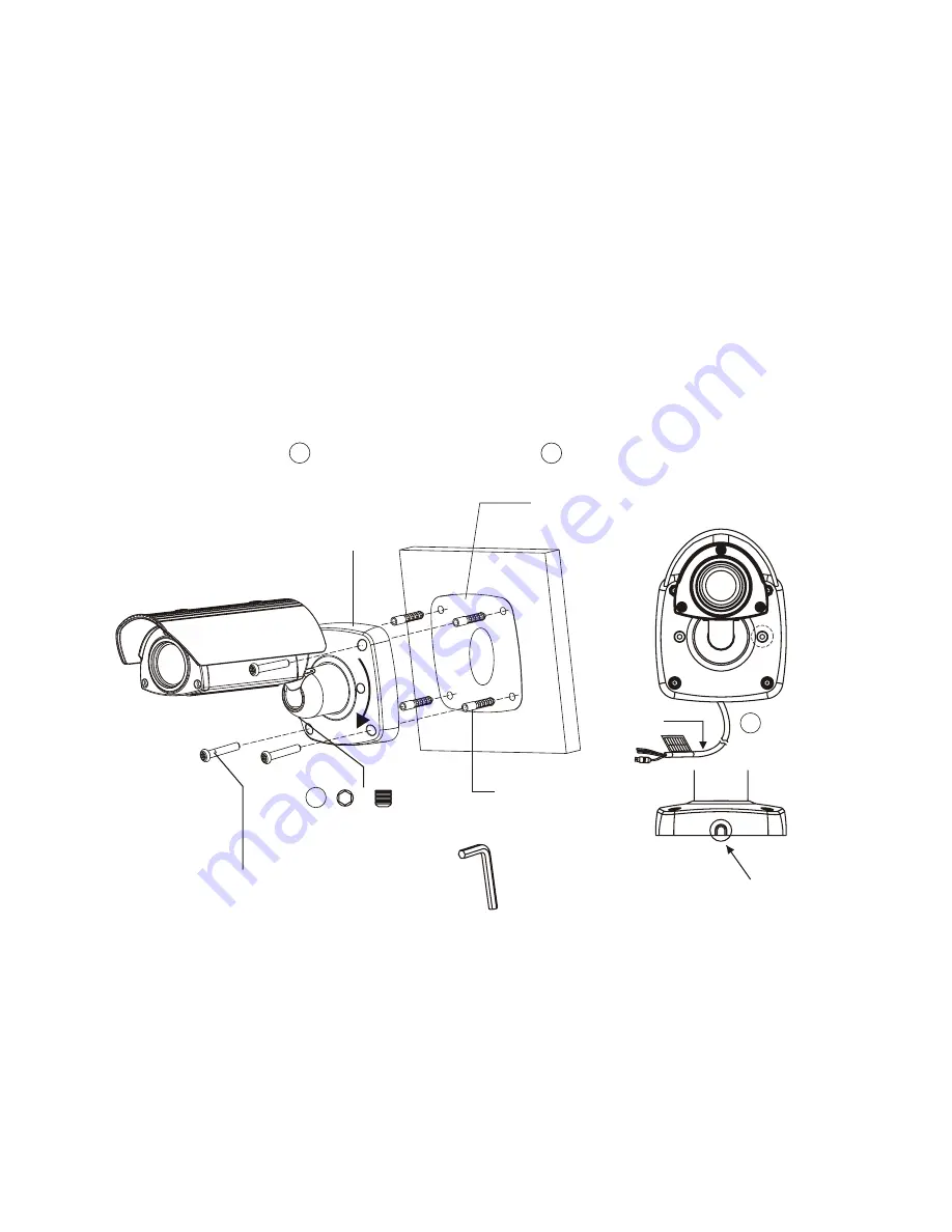
INSTALLATION 2


(Using the conduit knockout punched with Mount Base)

A. Drill the mounting location, using the template sheet (or the bottom of the 

    mount base) as a template.

B. Insert the plastic anchors into the hole which has just drilled.

C. Connect BNC cable and communication lines.

D. Fit the screw holes of the mount base into the plastic anchors.

E. Remove the conduit knockout punched for the cable entry.

F. Screw up the mount screws (T-20).

G. Adjust  the camera suitably using the pan & tilt function, and fasten both the 

   socket set screw     (1x) and torx lock screw      (2x) to fix the camera.

A conduit knockout punched 

for the cable entry

Socket Set Screw
M5.0, L=5.0mm

Plastic 
Anchors (4x)

Hexagon Wrench

Torx Screws (T-20)
M6.0 x 35.0 (4x)

Wall

Mount Base

Template Sheet

B

Torx Lock Screw 

(T-20)

Cable

A

A

B

Summary of Contents for XIN-VC-0622

Page 1: ...Please read this manual thoroughly before use and keep it handy for future reference Instruction Manual ALL IN ONE CAMERA COLOR CCD WEATHERPROOF AF D N ZOOM CAMERA ...

Page 2: ...RATE IN ALL RESPECTS HOWEVER WE CANNOT ASSUME RESPONSIBILITY FOR ANY CONSEQUENCES RESULTING FROM THE USE THEREOF THE INFORMATION CONTAINED HEREIN IS SUBJECT TO CHANGE WITHOUT NOTICE REVISIONS OR NEW EDITIONS TO THIS PUBLICATION MAYBE ISSUED TOINCORPORATE SUCH CHANGES ISSUE 1 JUNE 2006 ...

Page 3: ...ot going to be used for several days or more To disconnect the cord pull it out by the plug Never pull the cord itself Allow adequate air circulation to prevent internal heat build up Do not place the unit on surfaces rugs blankets etc or near materials curtains draperies that may block the ventilation holes Height and vertical linearity controls located at the rear panel are for special adjustmen...

Page 4: ...FERENCE TO RADIO COMMUNICATIONS OPERATION OF THIS EQUIPMENT IN A RESIDENTIAL AREAIS LIKELY TO CAUSE HARMFUL INTERFERENCE IN WHICH CASE THE USER WILL BE REQUIRED TO CORRECT THE INTERFERENCE AT HIS OWN EXPENSE CAUTION CHANGES OR MODIFICATIONS NOT EXPRESSLY APPROVED BY THE PARTY RESPONSIBLE FOR COMPLIANCE COULD VOID THE USER S AUTHORITY TO OPERATE THE EQUIPMENT THIS CLASS A DIGITAL APPARATUS COMPLIES...

Page 5: ...ete outlet 10 Protect the power cord from being walked on or pinched particularly at plugs convenience receptacles and the point where exit from the apparatus 11 Only use attachments accessories specified by the manufacturer 12 Unplug this apparatus during lightning storms or when unused for long periods of time 13 Refer all servicing to qualified service personnel Servicing is required when the a...

Page 6: ...THIS PAGE INTENTIONALLY LEFT BLANK vi ...

Page 7: ...STALLATIONS 3 4 CONNECTION 7 4 1 COLOR LEAD WIRE COLOR DISPLAY LABEL 7 4 2 EXTERNAL DAY NIGHT CONTROL 8 4 3 RS 485 CONNECTION 8 4 4 EXTERNAL LENS CONTROL 8 4 5 EXTERNAL A D KEY CONTROL 9 5 CAMERA ADJUSTMENT 10 5 1 OSD MAIN SCREEN 10 5 2 MAIN MENU 11 6 TROUBLESHOOTING AND MAINTENANCE 18 6 1 TROUBLESHOOTING 18 6 2 MAINTENANCE 18 7 SPECIFICATIONS 19 8 DIMENSIONS 20 ...

Page 8: ...on AWB Auto White Balance AE Auto Exposure AGC Auto Gain Control BLC Back Light Compensation OSD On Screen Display D Zoom Digital Zoom NEGA POSI Negative Positive B W Black White PIP Picture In Picture FREEZE Rear still picture MIRROR Right left reverse picture Excellent picture quality Various picture effects Dual power operation AC 24V DC 12V Use Certified Listed Class 2 power supply transformer...

Page 9: ...ocal national electrical and mechanical codes must perform installation of the camera Perform the following steps to install the camera 2 1 PACKAGE CONTENTS Camera 1EA Instruction Manual 1EA A D Remote Controller option 2 2 OPERATION REQUIREMENTS 2 J BOX CAMERA 1 MULTIPLEXER MONITOR CONTROLLER DVR VCR RS 485 RS 485 RS 485 VIDEO CAMERA 2 CAMERA 3 VIDEO ...

Page 10: ...IC ANCHORS 4X TORX WRENCH T 20 1X L TYPE HEX WRENCH 1X Carefully remove the contents from the box and verity that nothing was damaged in shipment 4 Point Drilling Position 50201623A 3 1 INSTALLATIONS 1 Cable through the wall with mount base 2 Using the conduit knockout punched with the mount base 3 Cable through the junction box with the mount base There are three ways of installing the camera ...

Page 11: ...C Connect BNC cable and communication lines D Fit the screw holes of the mount base into the plastic anchors E Screw up the mount screws T 20 F Adjust the camera suitably using the pan tilt function and fasten both the socket set screw 1x and torx lock screw 2x to fix the camera Socket Set Screw M5 0 L 5 0mm Hexagon Wrench Torx Screws T 20 M6 0 x 35 0 4x Wall Mount Base Plastic Anchors 4x Template...

Page 12: ...he screw holes of the mount base into the plastic anchors E Remove the conduit knockout punched for the cable entry F Screw up the mount screws T 20 G Adjust the camera suitably using the pan tilt function and fasten both the socket set screw 1x and torx lock screw 2x to fix the camera A conduit knockout punched for the cable entry Socket Set Screw M5 0 L 5 0mm Plastic Anchors 4x Hexagon Wrench To...

Page 13: ...ble through junction box with mount base The camera can be mounted on the junction box using the UNC 8 32 machine screws Junction Box Socket Set Screw M5 0 L 5 0mm Torx Screws T 20 UNC 8 32 x 0 75 4x not provided Hexagon Wrench ...

Page 14: ...DISPLAY LABEL 7 REMOTE CONTROLLER FAR MENU WIDE TELE NEAR MONITOR VIDEO BNC RS 485 CONNECTION Day Night CONTROL A D KEY CONTROL DVR VCR BLUE GREEN BROWN VIOLET GRAY WHT BLK LENS CONTROL BLACK ORANGE RED WHITE POWER CONNECTION COLOR PINK SKY BLUE BLACK WHT RED WHT BLK GRAY BLUE GREEN ORANGE VIOLET YELLOW BROWN DESCRIPTION TXD RXD GND AC 24 DC 12 AC 24 DC 12 EXT OUT EXT IN RS 485 RS 485 A D KEY FOCU...

Page 15: ...YELLOW WIDE GND BROWN External DC 3V to 12V YELLOW FOCUS NEAR External Power DC 3V to 12V VIOLET GND YELLOW FAR GND VIOLET External Power DC 3V to 12V BNC YELLOW FOCUS ZOOM COMMON YELLOW ZOOM BROWN FOCUS VIOLET COMMON YELLOW 4 2 EXTERNAL DAY NIGHT CONTROL Is connect to an external sensor to receive day night detection signals DAY NIGHT EXT IN GRAY GND BLACK Note To validate the sensor inputs selec...

Page 16: ...KEY2 Remote Controller 1 1 2 2 1 1 2 2 1 1 2 2 1 1 2 2 1 1 2 2 R22 150 R20 12K R21 5 6K Sw10 TELE R19 22K Sw11 WIDE Sw13 FAR Sw12 NEAR R18 33K Sw9 MENU A D KEY A D KEY ORANGE Remote Controller REMOTE CONTROLLER FAR MENU WIDE TELE NEAR 1m 3 86mm 40mm GND BLACK A D KEY WHITE ...

Page 17: ...T 5 1 OSD MAIN SCREEN Camera title Status of the auto exposure Status of the auto white balance Status of the focus mode Status of the zoom position brightness or sharpness Status of the shutter speed Status of the iris Status of the AGC auto gain control Camera ID 10 ...

Page 18: ...Auto white balance mode INDOOR Indoor white balance mode OUTDOOR Outdoor white balance mode MANUAL Manual mode You can change R and B Gain manually For changing R and B gain use NEAR and FAR key If you save the change and push the MENU key WAWB Wide range auto white balance mode WB AWB INDOOR OUTDOOR MANUAL R B WAWB END ...

Page 19: ...lay Low Shutter mode Mode can be changed in the preset menu WE AUTO IRIS PRI SHUTTER PRI AGC MANUAL END IRIS AGC SHUT LOWSHUT 5 2 3 BLC Back Light Compensation DEFAULT Default setting Center weight BLC ADJ TOP You can adjust BLC Zone in left and or top direction ADJ BOTTOM You can adjust BLC Zone in right and or bottom direction LEVEL You can adjust BLC level 0 90 Default value is 30 OFF BLC off B...

Page 20: ... right Erase a left character Erase a right character S Save title E End 5 2 5 DISPLAY DISP0 Display title and camera ID DISP1 Display title camera ID and zoom lens position DISP2 Display all camera status DISP Off On and push on Display on when any key is pressed DISPLAY DISP0 DISP1 DISP2 DISP PUSHON END ...

Page 21: ... x4 x8 x16 x32 x60 PROTOCOL Select operating protocol COMMAND Camera controlled by RS 232C command FASTRAX Fastrax protocol PELCO D Pelco D protocol PELCO P Pelco P protocol SAVE PROTOCOL BPS Save protocol and BPS NOTE 1 You can choose BPS menu appropriate for keyboard protocol NOTE 2 If you change BPS or PROTOCOL menu you have to select PROTOCOL BPS menu Although you change BPS or PROTOCOL menu t...

Page 22: ...EGA POGI Select the Negative or Positive picture B W Select Color B W picture or EXT mode MIRROR Select horizontal reverse picture PIP Picture In picture on off FREEZE Select real and still picture D N Day Night mode on off CAUTION Freeze mode is automatically off when zoom and focus operation 15 ...

Page 23: ...ital Noise Reduction mode on off SHOT Select Normal DIS WDR or Low Shutter mode DIS digital image stabilization WDR wide dynamic range Low Shutter low shutter speed mode In the WDR or Low Shutter mode AF performance and Image quality can be decrease DIS is operated on D Zoom X 2 DNR is disabled In freeze Low Shutter and WDR mode WDR is not effective in freeze status CAUTION PRESET FOCUS INIT LOAD ...

Page 24: ...THIS PAGE INTENTIONALLY LEFT BLANK 17 ...

Page 25: ...llowing maintenance A Inspect all connection cables for deterioration or other damage B Clean components with a clean damp cloth C Verify that all the mounting hardware is secure 18 PROBLEM POSSIBLE SOLUTION Nothing appears on the screen Are the power cord and line connection between the camera and monitor made properly The image on the screen is dim Is the lens dirty If so clean the lens with a s...

Page 26: ...nes B W 0 5 lux Color 0 05 lux B W 0 001 lux Low shutter 1 0 Vp p 75 ohm composite 52dB AGC off RS232 RS485 Fastraxll E Pelco D Pelco P A D key Auto Manual Push AF AWB Indoor Outdoor Manual WAWB Auto Iris PRI Shutter PRI AGC Manual Auto Manual F1 6 F32 On Off 30dB max Normal 1 10 000 Default ADJ Top ADJ Bottom Level Off A Z 0 9 On Off Push On DISP0 DISP1 DISP2 001 255 2400 4800 9600 19200 0 90 ste...

Page 27: ...8 DIMENSIONS FRONT VIEW 120mm 120mm 86mm 71 7mm SIDE VIEW 84mm 218mm 120mm 158mm 271mm REAR VIEW 308mm 120mm 120mm 85mm 85mm 4 6 4 SC HOLES 20 ...

Page 28: ...50302061A PRINTED IN KOREA AF D N ZOOM CAMERA ALL IN ONE ...

Reviews: