


Installation Steps
Part 1
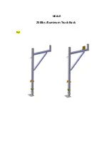
Fig 2-1
Part 1
The purpose of part one is to assemble the frame for the truck rack. Follow the instructions
below:
1.
To assemble the frame you will need the “Base”
and both “Frames”.
2.
On the side you prefer to have the truck rack on, place a “Base”
near the front and in
the back corners of the bed of the truck. Note that the “Base”
should be running
parallel to each other on the long side of the truck. Additionally, the long side of the
“Base”
should be parallel with the trucks side.
3.
After placing the bases, take the “Frames”
and slide one onto each “Base”. Note that
the cylinders on the top half of the “Frames”
should be facing the opposite side of the
truck.
Frame 2x
base 2x
Fig 2-2
Fig 2-3


