Disaster Area Designs DPC-5 Gen3 User Manual Download Page 4

 of 

4

28

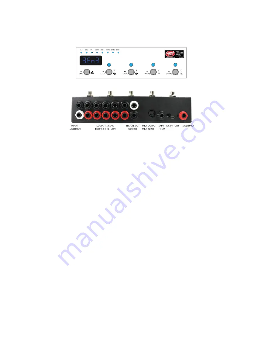
2.  Controls and Connections 

CONTROL PANEL

REAR PANEL

Input:  Connect your guitar or the output of an effects pedal here.
Tuner Out:  Connect the input of your tuner pedal here.  The Tuner Output is separately buffered and is always active.

Loop 1 Send - Return:

Loop 1 features a bypassable signal buffer.  Bypass the buffer in the DPC Setup menu to allow this loop to 

be used with impedance sensitive pedals such as germanium fuzzes, vintage wahs, etc.  Connect the black SEND jack to the input of 
each pedal, and the red RETURN jack to the output of the pedal.

Loops 2-5 Send - Return: Loops 2-5 have their own buffer section that is always active.  Connect the black SEND jack to the input of 
each pedal you would like to control, and the red RETURN jack to the output of the pedal.

TRS CTL Out:

The upper white jack is an isolated stereo / TRS connector designed to switch control functions on amplifiers or 

pedals.  No audio is carried on this jack, only switching signals.  This jack may be assigned to one of several types of control function 
including normally-closed, normally-open, momentary, or tap tempo.

Output: The lower black jack is the audio signal output.  Connect this to the next pedal in your chain or directly to your amplifier or 
recording interface, etc.  The output jack is separately buffered to ensure proper output impedance regardless of whether any pedals 
are engaged.

MIDI Output / MIDI Input: Standard 5-pin MIDI output, connects to your first MIDI pedal input.  The MIDI output jack doubles as a MIDI 
input using a Disaster Area MIDI Y-cable (sold separately.)  The MIDI input allows the DPC-5 Gen3 to accept incoming MIDI messages 
and merge them in with its own data stream.

Expression Input: The black jack is a multi-function connector that can accept an expression pedal or a momentary footswitch.  Starting 
in v1.01d the Expression jack may also serve as an additional MIDI out just like the MultiJack.  Consult the Expression section for more 
details.

DC 9V:

Standard DC power supply input, 9V center negative.  The DPC-5 Gen3 requires approximately 80mA if used by 

itself.  If an external USB HOST device is connected, the DPC-5 will need to be supplied with enough current to power both itself and 
the USB device.

USB MIDI:

The standard DPC-5 firmware allows the USB port to function as a MIDI interface for your compatible PC, Mac, or 

iPad (using the Apple Camera Connection Kit.)  The DPC-5 will receive and send MIDI messages over USB for device control.
USB HOST:

If the USB Host firmware is installed, the DPC-5 USB port may be used to send and receive MIDI messages to 

supported USB devices.

Status Indicator: This LED that blinks to let you know the pedal is working.  It also blinks at a slower rate to indicate that the pedal is in 
boot loader mode during a firmware update.

MultiJack:

The final jack on the panel is our astounding MultiJack!  The MultiJack can do all kinds of cool stuff, like receive 

expression or tap tempo, send taps to your devices, or even send MIDI to additional devices.

Disaster Area Designs 

DPC-5 Gen3

Summary of Contents for DPC-5 Gen3

Page 1: ...DPC 5 Gen3 User Manual v1 03...

Page 2: ...ans we lose looper pre post control since we need to assign its button to reverse Added commands to keep mute relay alive in host mode v1 00f Fixed an issue with the D preset button canceling the mute...

Page 3: ...pedals using the DPC 5 Gen3 effects loops The DPC 5 includes a single TRS tip ring sleeve jack with switching contacts these contacts may be assigned to a variety of functions including tap tempo or a...

Page 4: ...n MIDI output connects to your first MIDI pedal input The MIDI output jack doubles as a MIDI input using a Disaster Area MIDI Y cable sold separately The MIDI input allows the DPC 5 Gen3 to accept inc...

Page 5: ...looking at the back panel but when the DPC is in playing position the signal flows from RIGHT to LEFT as is common with guitar effects setups Connect a patch cable from Loop 1 send that s the black o...

Page 6: ...ssors auto wah filtering pedals etc 2 If you have a vintage style fuzz pedal that doesn t respond well to buffers place it in LOOP 1 then bypass the buffer in the DPC setup 3 Place your drive or disto...

Page 7: ...generally silence any troublesome pedals preventing them from popping or clicking when you change presets If the delay bothers you set POP OFF In most cases the popping won t be objectionable even wi...

Page 8: ...ed primarily for Roland Boss effects This function will disable CTL1 or CTL2 in manual mode instead assigning them to the Clock mode Please note that while the TRS Amp Control jack is isolated from th...

Page 9: ...some devices that won t re transmit MIDI or that will mangle interfere drop messages so sometimes you have to get creative with your routing Each MIDI device receives commands on one or more MIDI cha...

Page 10: ...SAVE to save the setup and start using the controller Here s how to set up your devices Enter setup as described above The first menu you ll see is PRST which allows you to select the number of availa...

Page 11: ...the factory In order for these devices to recognize the commands we send a few parameters must be set in their MIDI menus If using H9 Control navigate to Pedal MIDI Settings MIDI Channel Set MIDI Rec...

Page 12: ...ce setup is needed but note that the DPC 5 Gen3 can only use the MultiJacks that have been configured as TOGG in Setup DISASTER AREA DPC 8EZ SMARTCLOCK SMARTLOOP If you are connecting to a Disaster Ar...

Page 13: ...t save if PROT ON in Setup A Load the A preset for the current bank or bypass if A was previously selected Hold to select the next lower bank B Load the B preset for the current bank or bypass if B wa...

Page 14: ...8th and 8th Triplet D Tap Tempo In the Setup Menu there are four options for Clock Mode each with different levels of functionality so that the user can decide the type of tempo control Disaster Area...

Page 15: ...ps Device Mode for manually changing settings on your MIDI devices Scroll around until you find a sound you like then move to the next device and do the same When you ve got all of your devices set wh...

Page 16: ...h and begin overdubbing Tap again to stop overdubbing and enter playback You may tap this button at any time while the loop is recording to overdub additional parts HOLD to toggle reverse normal loop...

Page 17: ...d like to change the loop names you can enable the Loop Names option in the DPC 5 Setup menu Simply navigate to the LNAM option and set it to either ON or SCRL If LNAM is set to OFF generic loop names...

Page 18: ...preset while in Preset Mode the DPC 5 Gen3 will bypass by loading the zero preset If you would like to use the zero preset as a favorite sound you can overwrite the default values just like any other...

Page 19: ...uipped with a side roller potentiometer as a factory option In previous versions of the DPC 5 series the side roller shared an input channel with the external expression input and the two could not be...

Page 20: ...channel selection A B C MultiJack enable disable If the location shows as zero the controller will not transmit expression or MIDI on that channel If all three locations show as zero and the MultiJack...

Page 21: ...JACK to T NC for Boss devices or T NO for most other devices SET J CH TO ABC SET DIP SWITCHES to OFF OFF OFF If you re connecting a Boss pedal you should set the MultiJack to N C Most other pedals req...

Page 22: ...d CTL2 reverb to NC That will make sure that both trem and reverb are ON when the DPC 5 lights are ON Once you have set everything up just connect the white TRS jack to your amplifier using a stereo T...

Page 23: ...r into the DPC 5 Gen3 and that s it You can now control the Zoom pedal just like any other pedal Their MIDI support is limited but you can change presets and engage the tuner USB MIDI If you want to c...

Page 24: ...re details 7 Press the mode button on the Gen3 to start the transfer The display will update to alert you to the transfer status 8 This should result in a data transfer being sent to your computer whi...

Page 25: ...sion Pedal enable disable If the location shows as zero the controller will not transmit expression or looper level on that channel If all three locations show as zero no expression will be sent JACK...

Page 26: ...k name will scroll when loaded then the first four characters of the bank name will display LNAM Loop Name Display OFF Generic loop names will display if loops change ON first four characters of the l...

Page 27: ...ite delay Strymon Mobius Mobius MOBI CC100 NO NO Strymon BigSky BigSky BSKY CC100 NO NO LTC sends command for freeze infinite Chase Bliss ALL ChasBlss CBA CC100 NO NO Boss DD 500 MD 500 RV 500 DD 500...

Page 28: ...Meris setup mode to assign EXP port to MIDI Boss SY 300 BOSS SY 300 SY 3 CC7 CC24 NO GFI System Specular Tempus GFI SPECULAR GFI NO NO NO NONE MIDI Notes MIDI Notes NOTE CC7 CC69 NO Special sends MID...

Reviews: