background image

Operating Instruction

36

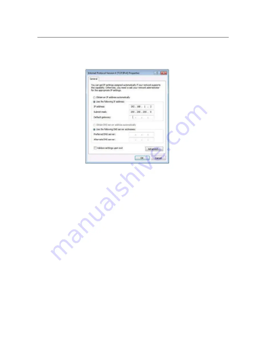
6). Select

Use the following IP Address

for static IP addressing and fill in the details.

For TCP/IPv4 you can use any IP address in the range 192.168.1.2 to 192.168.1.254 (excluding

192.168.1.168).

Change IP address interface (picture-58)

7). Click

OK

.

8). Click

Close

.

Enter Web and Control

Enter the default IP address of the matrix: 192.168.1.168
Account: admin
Password: 123456

12. STATUS INTERFACE

Status interface include 3 parts: input information, output information and device version information
1. Input info: Displays the status and information of the current device input port, Includes the connection
status, input resolution, gamut color depth, HDCP version information and input audio format of each
input port.
2. Output EDID info: Displays the status and information about the output port, Includes the connection
status, output resolution and color gamut, output audio format, EDID manufacturer of each output port.

Summary of Contents for 20111545

Page 1: ...Operating Instruction 1 8x8 HDMI2 0 Matrix Support 4K 60hz YUV4 4 4 18Gbps HDR Best nr 20111545 ...

Page 2: ...y to persons To prevent fire or shock hazard do not expose the unit to rain moisture or install this product near water Never spill liquid of any kind on or into this product Never push an object of any kind into this product through any openings or empty slots in the unit as you may damage parts inside the unit Do not attach the power supply cabling to building surfaces Use only the supplied powe...

Page 3: ...7 5 3 Menu settings 21 7 5 4 User EDID settings 22 7 5 5 System settings 23 7 6 Device information query 25 7 7 Remote Control Description 29 8 AUDIO INTRODUCTIONS 30 8 1 HDMI audio 30 8 2 Audio extraction 30 8 2 1 Analog audio extraction 30 8 2 2 SPDIF audio extraction 30 8 3 Audio embedded 30 8 4 ARC audio 30 9 EDID MANAGEMENT 31 10 RS232 CONTROL 32 11 WEB CONTROL 34 11 1 Address Information 34 ...

Page 4: ... major control systems This unit also supports HDR10 to bring ultimate visual experience It is designed to save end users time and energy for they are able to update the system by the creative RS232 interface 2 APPLICATIONS Video TV wall display and control Security surveillance and control Commercial advertising display and control University lecture hall display and control Retail sales and demo...

Page 5: ...GUI The Ethernet port supports Telnet UDP HTTP and TCP IP Support EDID management CEC and ARC 6 SPECIFACATIONS Bandwidth 18 Gbps Resolution 480p 60hz 576P 50hz 720P 60hz 1080P 24hz 1080P 50hz 1080P 60hz 4K 24hz 4K 30hz 4K 60hz YUV4 2 0 4K 60hz YUV4 4 4 Video Input Connectors 8xHDMI Type A 19 pin female Video Output Connectors 8xHDMI Type A 19 pin female Audio Input Connectors 8xAnalog audio 3 5mm ...

Page 6: ...CD Showing Matrix information Output button OUT1 8 Input button IN1 8 Function button PRESET MENU UP DOWN LOCK ENTER 7 2 Rear Panel 1 AUDIO IN Analog x8 IR port 2 AUDIO OUT Analog x8 Grounding 3 AUDIO OUT SPDIF x8 HDMI Input 8 4 Ethernet port HDMI Output 8 5 RS232 Power on off ...

Page 7: ... as the output channel 5 select the key 5 and press it again to cancel the selection Long press output any channel number to select all channels and long press again to cancel After press the button no next operation is performed within 10 seconds and the operation state ends MENU Function Button Enter the function option or back to previous option Long press back to function option the next step ...

Page 8: ...ideo switching mode picture 3 Switch the input to the output Operation format output channel input channel For Example Output port 1 3 4 switch to input 3 Operation Press OUT number 2 5 8 IN number 7 to complete the switch For Example Switch all outputs to input 4 Operation Long press input number 4 to complete the switch Output signal Control Output interface has nine sub menus Output1 Output8 an...

Page 9: ... 8 or All The bottom color of the selected output port becomes white Press Enter enter next page Press UP DOWN button to select Video press Enter Press UP DOWN button to select Source press Enter Press UP DOWN button to select Source press Enter Press UP DOWN button to select Input 1 8 press Enter switch done Press MENU button back to previous option Press UP DOWN button to select Onoff Press Ente...

Page 10: ...ault Operation instructions turn off other audio is same Select Output and press ENTER Press UP DOWN button to select Output1 8 or All meas all outputs The bottom color of the selected output port becomes white Press Enter Press UP DOWN button to select Audio Press ENTER Press UP DOWN button to select the mode HDMI Analog SPDIF ARC press ENTER Press UP DOWN button to select On Off output audio on ...

Page 11: ...ure 9 Output audio on off interface picture 10 7 3 4 Input signal control Input signal control interface has nine sub menus Input1 8 and All means all inputs The third level sub menu includes Video Audio and EDID settings Input option interface picture 11 ...

Page 12: ...tion instructions Select Input Press ENTER Press UP DOWN button to select Input1 8 or All Press ENTER Press UP DOWN button to select Video Press ENTER Select Onoff Press ENTER Press UP DOWN button to select On Off On off input video done Input video control interface picture 13 On off input video interface picture 14 ...

Page 13: ...ENTER Press UP DOWN button to select Audio Press ENTER Press UP DOWN button to select Source Press ENTER Press UP DOWN button to select HDMI ENC Press ENTER The selected off on show Press MENU then press UP DOWN button to select Onoff Press ENTER Press UP DOWN button to select On Off input audio on off done Input audio settings interface picture 15 Input audio source choose interface picture 16 On...

Page 14: ...emporary EDID Operation instructions Select Input Press ENTER Press UP DOWN button to select Input1 8 or All Press ENTER Press UP DOWN button to select EDID Press ENTER Press UP DOWN button to select EDID Default1 Press ENTER setup complete The selected EDID will show EDID details name Max resolution audio format sound track EDID settings interface picture 18 EDID information interface picture 19 ...

Page 15: ...peration instructions Select Preset Press ENTER then enter preset scene interface Save preset Select Save on preset interface then select one of Preset1 8 Press ENTER save current scene Call preset Select Call on preset interface Select one of the saved preset1 8 presets Press ENTER Call the preset scene saved previously Clear preset Select Clear on preset interface Select one of the saved preset1...

Page 16: ...m parameter System configuration interface picture 23 Network parameter settings Set DHCP IP MASK GW Port DNS MAC 1 DHCP Default Off Static After turn on Dynamic IP MASK GW are unable to set 2 IP address Default 192 168 1 168 3 MASK address Default 255 255 255 0 4 GW Default 192 168 1 1 5 PORT TCP UDP port Default TCP 5000 UDP 5001 6 DNS Default 144 144 144 144 unalterable Operation instructions ...

Page 17: ...off DHCP Press MENU Select IP MASK GW Port DNS MAC Press ENTER Such as change IP address After select IP enter and select Part 1 4 then Set IP address parameters for each part Press Enter again LCD ll show the current network parameters Do the same for other parameters Network parameter settings interface picture 24 DHCP settings interface picture 25 IP settings interface picture 26 ...

Page 18: ...provide 6 choices 115200 57600 38400 19200 9600 4800 The device is 115200 by default 2 Data Stop Parity is used only for view and cannot be changed Unless use the highest account 3 The underscore show that this parameter cannot be set Operation instructions Select Config Press ENTER Press UP DOWN button to select RS 232 Press ENTER Press UP DOWN button to select Baud Press ENTER Press UP DOWN butt...

Page 19: ...ontrol interface picture 29 Baud rate set interface picture 30 Data display interface picture 31 7 5 2 LCD screen settings You can set LCD screen s bright and Screen rest time Bright is 8 by default Screen rest time is 30S by default ...

Page 20: ... UP DOWN button to select LCD brightness level The higher the brightness level the greater the brightness otherwise the lower the brightness Press MENU then press UP DOWN button to select Time Press ENTER Press UP DOWN button to select screen rest time LCD settings interface picture 32 LCD brightness settings interface picture 33 Screen rest time settings interface picture 34 ...

Page 21: ...e to switch level directly Unless you get client access and then switch by command Note that a low level can t set a high level Operation instructions Select Config Press ENTER Press UP DOWN button to select Menu Press ENTER Press UP DOWN button to select Time Press ENTER Press UP DOWN button to select the time you need Press MENU Press UP DOWN button to select Select run Press ENTER Press UP DOWN...

Page 22: ...D and temporary EDID to the User EDID Operation instructions Select Config Press ENTER Press UP DOWN button to select User EDID Press ENTER Press UP DOWN button to select User1 4 or ALL Press ENTER Press UP DOWN button to select default EDID output EDID or temporary EDID to save User EDID while you can check EDID information User EDID settings interface picture 39 ...

Page 23: ...u can set device s Reboot Timing switch Factory data reset 1 Reboot Restart device Operation instructions Select Config Press ENTER Press UP DOWN button to select System Press ENTER Press UP DOWN button to select Reboot Press ENTER Press UP DOWN button to select Yes Press ENTER Device Reboot done System settings interface picture 42 ...

Page 24: ... Operation instructions Select Config Press ENTER Press UP DOWN button to select System Press ENTER Press UP DOWN button to select Timing Press ENTER Press UP DOWN button to select Off On Press ENTER Press UP DOWN button to select time you need Timing switch interface picture 44 Timing switch time interface picture 45 3 Factory data reset Device function initialization Settings ...

Page 25: ...DOWN button to select System Press ENTER Press UP DOWN button to select General Press ENTER Press UP DOWN button to select Yes Device factory data reset done Factory data reset interface picture 46 General factory data reset interface picture 46 Factory data reset range interface picture 47 7 6 Device information query Device information input information output information system information ...

Page 26: ...ns Select INFO Press ENTER Press UP DOWN button to select Input Output Press ENTER Press UP DOWN button to select input output port then see input output information Device information interface picture 48 Input port choose interface picture 49 Input information display interface picture 50 3 System interface is used for checking device system information Manufacturer Device ID device type Version...

Page 27: ... to select Device Versions Network then you can check information Input information display picture 51 Input information display picture 52 Input information display picture 53 4 LOG it used for checking device information running time startup times operation times runs errors times Input information display picture 54 ...

Page 28: ...Operating Instruction 28 Input information display picture 55 ...

Page 29: ...k panel button Choose output from 1 8 Choose all the outputs X Turn on off output port which you select PTP button Mirror all inputs and outputs Ex Input 1 to output 1 input 2 to output 2 etc Choose Input from 1 8 Menu back to previous option button UP button Enter button DOWN button ...

Page 30: ...io output will not be affected Analog audio only support PCM2 0 otherwise Auto Mute Analog audio left and right channels cannot be reversed output Analog audio will Auto Mute when digital audio input 8 2 2 SPDIF audio extraction When the 8 8 matrix is selected for one to one output the coaxial audio output can only output the audio of the port When the HDMI output port is muted coaxial and analog ...

Page 31: ...ontrol EDID by WEB and RS232 Factory Default Default1 4K60 444 2CH The instructions are follow 1 Send instruction edid_d in 8 d source d switch EDID in 8 d parameter need to input 255 or 0 7 255 means all input source d 0 24 Correspond the table below EDID MODE EDID Index EDID Default EDID 0 4096x2160 60 444 HLG 2CH default 1 4096x2160 60 420 HLG 2CH 2 4096x2160 30 444 HLG 2CH 3 1920x1080P 120 444...

Page 32: ...lustrated with SSCOM32 as an example Basic Settings Double click the software in the installation package to run specifically as shown in figure 1 below and install the RS232 software on the computer Enter the main interface of the software as shown in the figure below RS232 control interface picture 56 ...

Page 33: ...ead Parameter1 Parameter2 need to add one SPACE The following table is only an example Please refer to the list of instructions Type format data Rule instructions video_ c d data Target 1 in 8 d 0 7 assign port 255 all port parameter 2 attributes are available Target 2 out 8 d 0 7 assign port 255 all port All parameter attributes are available Parameter 1 source d 0 7 input channel Parameter 2 ono...

Page 34: ...ress of your PC 1 Connect the HDMI Matrix and PC to the LAN 2 Configure your PC as follows Click Start Control Panel Network and Sharing Center Click Change Adapter Settings Highlight the network adapter you want to use to connect to the device and click Change settings of this connection 3 Connect to the device and click change settings of this connection 4 Highlight Internet Protocol Version 4 T...

Page 35: ...Operating Instruction 35 Change IP address interface picture 57 ...

Page 36: ...ccount admin Password 123456 12 STATUS INTERFACE Status interface include 3 parts input information output information and device version information 1 Input info Displays the status and information of the current device input port Includes the connection status input resolution gamut color depth HDCP version information and input audio format of each input port 2 Output EDID info Displays the sta...

Page 37: ... the current name of input port support 1 15 characters numbers letters and underscores which is synchronized with the screen 2 Video Switch input video Once the input video is off the audio extraction output is muted 3 Audio Switch audio of audio source include HDMI and embedded audio The default is on 4 Audio Source Switch audio source HDMI select input source audio ENC select embedded audio inp...

Page 38: ...o Click the two way button to complete the switch setting of input video and audio Green means on and gray means off 3 Audio source Use the mouse to click the white combobox to switch the corresponding input audio source 4 Copy EDID from Use the mouse to click the white combobox to complete the corresponding EDID switch The combobox ll show the current EDID information Copy EDID from picture 61 ...

Page 39: ... default switching audio output HDMI Analog SPDIF ARC function off by default 1 Rename Modify the current name of output port support 1 15 characters numbers letters and underscores which is synchronized with the screen 2 Video Switch output video close the output port video does not affect the audio extraction function the 5V output needs to be turned off at the same time 3 Audio HDMI Switch HDMI...

Page 40: ...tput the image Vertical axis means output port selection abscissa axis means input port selection All means select all output Matrix interface picture 63 Operation instructions Click the input box to switch the corresponding output port The above picture show the PIP one to one output 12 4 Preset interface Interface introduction The page is used for renaming saving calling and clearing of preset s...

Page 41: ...lear scene clear done 3 Click Save save the current scene 4 Click Call call the saved scene 12 5 CEC control interface Interface introduction By web page control the switch of input source or output TV and settings of volume increase and decrease but the prerequisite is input source and output TV support CEC function Page all English corresponding remote control functions ...

Page 42: ...ome signal sources and TVs in the market 12 6 System interface Interface introduction The page can modify and show network parameters and control protocol parameters modify web login account and password reboot device general restore factory user restore factory 1 Mac address can only be displayed and cannot be modified 2 IP address is 192 168 1 168 by default it can be modified After DHCP is open...

Page 43: ...en DHCP Green button means open DHCP Gray means close DHCP 5 Account management Enter your account and password in the white box Click Apply It takes effect on next login support 1 15 characters numbers letters and underscores 6 Click Reboot Factory General Factory User click enter according to the prompt Device Reboot restore factory done System interface picture 65 ...

Page 44: ...umber and select the correct serial port number 3 Baud data is 115200 by default 4 Input A1 on the port Select the path where the program resides to upgrade the MCU 5 Input F0 on the port Select the path where the program resides to upgrade the web page Click Update the system start to update until Succed is displayed in the information bar update done Upgrade interface picture 66 ...

Page 45: ...Operating Instruction 45 14 CONNECTION DIAGRAM ...

Page 46: ...ly or exhibits a marked change in performance The unit has been dropped or the cabinet damaged 2 Servicing Personal Do not attempt to service the unit beyond that described in these operating instructions Refer all other servicing to authorized service personal 3 Replacement parts Please ensure the defective parts to be replaced by manufacturers or the same specifications as the original parts Una...

Page 47: ...quired for Limited Warranty service This Limited Warranty ONLY COVERS failures result from defective materials or workmanship and DOES NOT COVER normal wear and tear or cosmetic damage The Limited Warranty ALSO DOES NOT COVER damages which occurred in shipment or failures which are caused by products not supplied by warrantor or failures which result from accidents misuse abuse neglect mishandling...

Reviews: