3
DirectConnect®
Houston, TX 77027
Tel: 800-531-3224
Fax: 713-525-3220
www.DirectConnectHome.com
The LED Indicators will allow you to monitor, diagnose and troubleshoot any
potential problem with the switch, connection or attached devices. The following
chart shows the LED indicators of the Switch along with explanation of each indicator.
LED
COLOR
STATUS
STATUS DESCRIPTION
Power
Green
On
Power On
Off
Power off
LINK/ACT
Green
On
Connect to the port
Off
Disconnect to the port
Flashing
Sending or receiving data
2.2 Rear Panel
The rear panel of the switch consists of 8 x 10/100/1000Mbps RJ-45 ports shown as
below.
These ports are connection points for PCs and other network devices, such as
additional switches or routers.
2.3 Side Panel
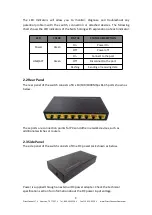
The side panel of the switch consists of One DC power Jack shown as below.
Power is supplied through an external DC power adapter. Check the technical
specification section for information about the DC power input voltage.


