Dion F67 Operator'S Manual Download Page 34

34

F6715E968

ADJUSTMENTS - MAINTENANCE
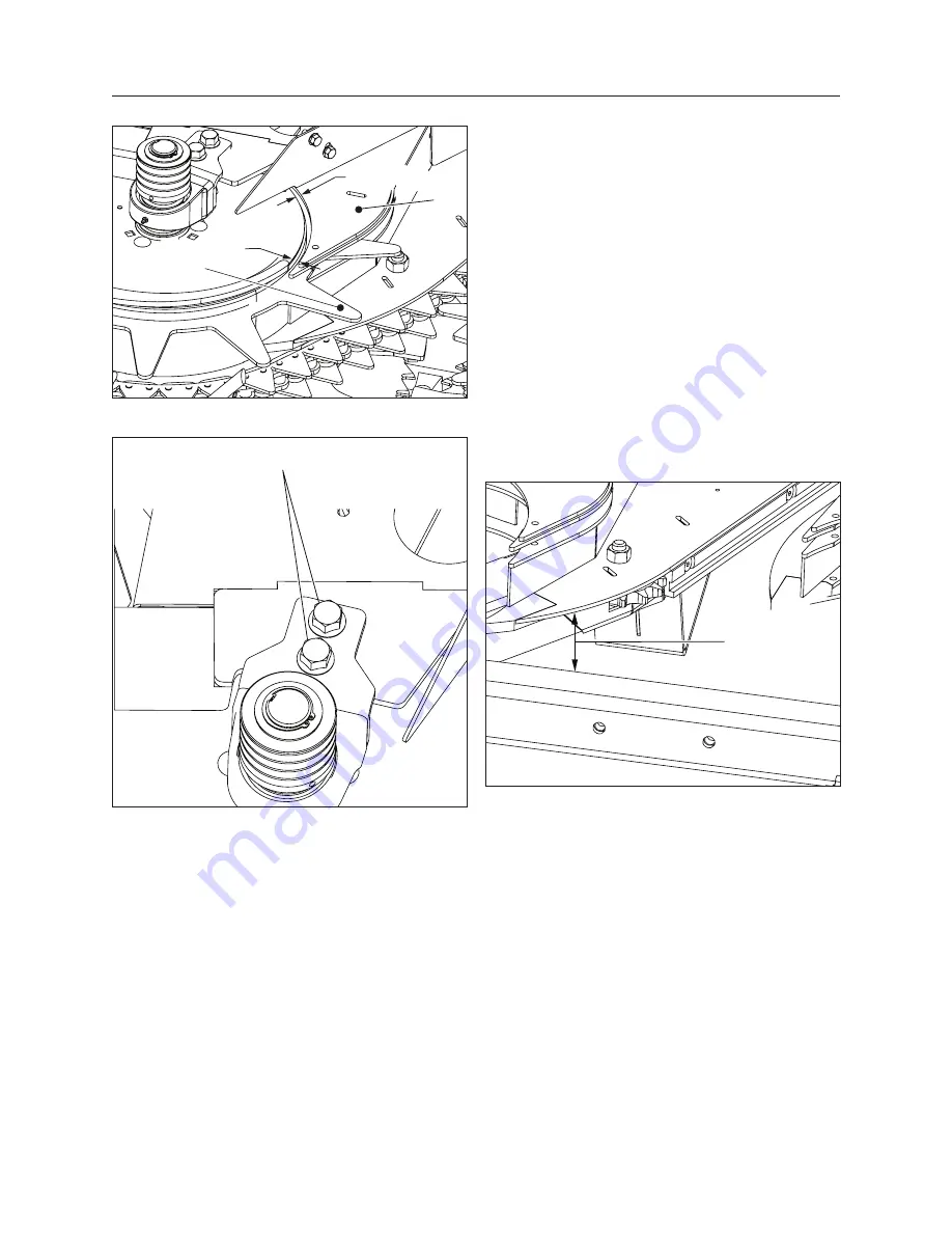
1/8" (3 mm)

1/4" (6 mm)

4

5

Figure 49  Drum adjustment

6

Figure 50  Drum support bearing bolts

SCRAPER ADJUSTMENT - FIGURE 51 

It may be necessary to adjust the scrapers after they 

have been moved or replaced.  
1.  Remove the drums.
2. 

Loosen the scraper bolts.

3.   Align the chain channel ridge with the frame 

ridge (figure 51).

4. 

 Position the scraper to obtain 6” (152 mm) be

-

tween the cross beam and the bottom of the 

scraper’s lower plate (figure 51). 

5.  The holes in the frame allow for a minor scraper 

adjustment. 

6.   Tighten all bolts back then check alignment and 

position.

7.  Reinstall the drums by following the drum 


adjustment instructions. 

6" (152 mm)

Figure 51  Scraper adjustment

Summary of Contents for F67

Page 1: ...Operator s Manual 2 Row Rotary Corn Attachment 1 5m Manual no F6715E968 F67 ...

Page 2: ...employee or representative of Dion Ag Inc has the authority to amend or modify in any manner whatsoever the terms of the present warranty The express warranties herein contained exclude all other express implied or statutory warranties THIS WARRANTY IS IN LIEU OF ALL OTHER WARRANTIES INCLUDING THE WARRANTIES OF MERCHANTABILITY AND OR FIT NESS FOR ANY PARTICULAR PURPOSE Right to Inspect Dion Ag and...

Page 3: ...ed you with a valuable tool for operating and maintaining this fine machine Use this manual as your guide Following the instructions given here will result in many years of dependable service from your machine Your Dealer can give you assistance with parts and specially trained personnel to assist you in repair and maintenance Call your Dealer if you need any assistance or information ...

Page 4: ...4 F6715E968 ...

Page 5: ...2 CHAIN LUBRICATION 22 TIGHTENER ROD LUBRICATION 23 GEAR BOXES OIL LEVEL 23 TIGHTENER GREASING 23 OVERRUNNING CLUTCH GREASING 23 DRUM GREASING 24 ADJUSTMENTS MAINTENANCE 25 GROUND CLEARANCE ADJUSTMENT 25 CONVEYOR CHAIN TENSION ADJUSTMENT 25 CONVEYOR CHAIN VERIFICATION 26 CHAIN SYNCHRONIZATION 28 CHAIN REPLACEMENT 29 INTERMEDIATE CHAIN TENSION ADJUSTMENT 29 DISK CLEANER ADJUSTMENT 30 KNIFE SECTION ...

Page 6: ...he F67 model Shipping Dimensions F67 F67 Dion F67 John DeereTM F67 NewHollandTM CaseIHTM Overall Length 189 cm 74 5 205 cm 80 5 205 cm 80 5 203 cm 80 Overall Width 200 cm 79 200 cm 79 200 cm 79 200 cm 79 Overall Height 122 cm 48 122 cm 48 122 cm 48 122 cm 48 Weight 500 kg 1100 lbs 540 kg 1188 lbs 525 kg 1155 lbs 530 kg 1166 lbs SPECIFICATIONS ...

Page 7: ...illustrated below Always mention both the model and the serial numbers when ordering parts or regarding any other correspondence referring to your machine Write down your number here MODEL NO SERIAL NUMBER SERIAL NUMBER LOCATION R H DROIT REAR ARRIÈRE L H GAUCHE FRONT DEVANT DFE MADE IN CANADA D F E INC BOISBRIAND QUE MODEL NO SERIAL NO PAR BY ...

Page 8: ...oose or missing bolts and parts Make sure no safety decal is missing and make sure they are readable Check condition of saw teeth Check condition of drum fingers Make sure they are solid and straight Check oil levels on gear boxes DAILY Check tension of belts and chains Clean machine Lubricate following instructions found in maintenance section Make sure all guards are in good condition CHECK LIST...

Page 9: ...me The Com pany reserves the right to make changes at any time without notice The safety section of your Operator s manual is in tended to point out some of the basic safety situ ations which may be encountered during the nor mal operation and maintenance of your F67 Rotary Corn Attachment and to suggest possible ways of dealing with these situations This section is NOT a replacement for other saf...

Page 10: ...and know the safety rules and regulations for the job Some local regulations specify that no one under the age of 16 years for example may operate power ma chinery This includes tractors It is your responsibility to know what these regulations are and obey them in the operating area or situation These will include but are not limited to the following instructions for proper operation WARNING An op...

Page 11: ...d feet away from the pick up chains and the saw Make sure all rotating parts are stopped and the tractor engine is turned off before cleaning the machine throat Never park the attachment in the transportation position Lower the attachment to the ground first Before starting the tractor engine make sure all guards shields and doors are in place and prop erly secured and check the machine thoroughly...

Page 12: ...be well con nected and kept in good condition Never step across any driveline Never use the driveline as a step Keep at least your height away from a rotating driveline STOPPING PROCEDURES No matter what type of machine is being used it is extremely hazardous to perform any kind of main tenance work while the machine is running Before cleaning adjusting or greasing the following pro cedures should...

Page 13: ...r the driving belts items 1 in fig ure 1 Figure 1 Drive belt guards item 1 and conveyor chain guard item 2 Hinged guards cover the conveyor chain items 2 in figures 1 and 2 Figure 2 Conveyor chain right guard An hinged guard covers the intermediate chain item 3 in figure 3 An hinged guard covers the drive shaft item 4 in figure 3 3 4 Figure 3 Intermediate chain guard item 4 and drive shaft guard i...

Page 14: ...decals should be in place and maintained in good condition Decals should be readable at all times 6 Figure 4 Safety sign location 6 1 5 Figure 5 Safety sign locations 6 5 Figure 6 Safety sign locations 4 7 6 1 8 3 2 1 Figure 7 Safety sign locations R H side ...

Page 15: ...rial 2 When the surface is dry remove a portion of the backing paper and apply the decal in part and align its position as per the surrounding parts Slowly peel off the remaining backing paper and apply hand pressure 3 Press slightly on the surface of the safety sign to remove all air bubbles Figure 8 Safety sign location L H side 6 6 1 8 1 1 9 ...

Page 16: ...livered with a temporary lifting arm for the removal of the skid item 3 IMPORTANT The lifting arm item 3 should not be used for moving or lifting the attachment It should only be used for laying it flat on the ground 3 Before removing the skid inspect bolts item 4 on disks fingers knife deflectors and drum bearings 4 Pass a chain item 5 with a minimum capacity of 1500 lbs 680 kg in the arm hook an...

Page 17: ...op of the frame 10 Refer to the installation instructions of the adap tor provided in the box The installation is done by the dealer before deliv ery to the client Contact your Dion representative if needed Figure 10 The 2 Row Rotary Corn Attachment in shipping position Long forks only 8 fourches longues seul 8 5 ...

Page 18: ...t come in contact with the feed rolls 3 Slowly move the Forage Harvester toward the attachment figure 13 making sure it is well centered with respect to the connecting pins 4 Align and adjust the attachment throat sides be tween the Forage Harvester sides and the feed rolls figure 14 5 When the attachment is set in place on the For age Harvester put the square lock pins and the safety pins back in...

Page 19: ...e handle item 3 Two balancing springs are required to op erate your attachment Bolt the spring bracket item 5 on the attaching bar item 6 as shown Tighten bolt item 7 well then install both bal ancing springs 8 Adjust the cylinder stroke to prevent the attach ment from touching the feed rolls INSTALLATION Figure 17 Balancing springs set up when using a Rotary Corn attachment ...

Page 20: ...ge Harvester lifting arms in op erating position Bring the chain underneath the tightening sprocket item 2 figure 18 as shown Align the drive chain Adjust the chain to a nor mal tension loosen nut item 4 figure 19 tight en tightener nut item 3 figure 19 then tighten nut item 4 figure 19 NOTE On Forage Harvester models prior to 2006 it will be necessary to cut out a notch in the Forage Harvester tr...

Page 21: ... contact and friction After the first few hours of operation check the fol lowing items Chains and other moving parts will re quire an adjustment after the break in period Adjust the chain tension refer to the Adjustment section Lubricate the chain refer to the Lubrication sec tion Locate and adjust the cleaning components and the scrappers in order to elimate any possible knocking and friction WA...

Page 22: ... and of the season F61 26340P 80W90 or equivalent Oil level Gear box 2 places S55 24592P Verify at beginning of each season and every 40 hours of operation Greasing Grease the chain tightener every day and the over running clutches under the guard ap proximately every 40h Over greasing the clutches may impair their proper function The gathering drum bearings 4 each are greasable They are lubricate...

Page 23: ...E 25 ITEM 1 IMPORTANT Check oil level on gear boxes before each season and every 40 hours of operation 1 Figure 25 Checking gear box oil level with gauge supplied TIGHTENER GREASING Grease the chain tightener item 3 in figure 24 lo cated under the left and right guards with one pump stroke every 8 hours OVERRUNNING CLUTCH GREASING Grease the overrunning clutches located under the belt guards Refer...

Page 24: ...the end of each sea son grease the drum bearings 4 on each drum The lower bearing is accessible under the skid and the two internal bearings are accessible through the top see figure 26 The upper bearing is located under the belt guard figure 27 Figure 26 Figure 27 LUBRICATION ...

Page 25: ... machine with blocs see safety section GROUND CLEARANCE ADJUSTMENT In order to prevent an early wear of the machine or a mechanical break down it is important to adjust the ground clearance For corn harvest it is recom mended to adjust the ground clearance to 12 inches 30 cm This is the actual distance between the ground and the saw blade This adjustment is done through the Forage Harvester s hydr...

Page 26: ... 34 Check chain stretch every 40 hours of operation or at the end of the season The chain has two cou pling links When the chain is half worn it is possible to reduce its length by removing one link in order to reposition the tighteners figure 34 When chain stretch exceeds 3 it must be replaced Use the special gauge located under the right chain guard figure 32 This gauge is supplied with the atta...

Page 27: ...27 F6715E968 ADJUSTMENTS MAINTENANCE Figure 34 Measuring chain stretch 3 wear replace conveyor chains New Chain 1 5 wear Shorten the chain by removing one of the two coupling links ...

Page 28: ...ing the belts or for any other reasons it may be necessary to remove the chain from the couplers item 1 figure 36 located underneath the gear boxes To easily re synchronize the conveyor chains mark with a line the alignment of the coupler teeth item 1 figure 36 1 Figure 36 To synchronize it is much easier to adjust only the position of the right vertical shaft First slightly loos en the chain tens...

Page 29: ...re 38 Special links and O ring 6 Synchronize the chains if necessary 7 Retighten the chains INTERMEDIATE CHAIN TENSION ADJUSTMENT FIGURE 39 The intermediate chain must be kept tight at all times Regularly check chain play and adjust if nec essary The chain play should not exceed 1 4 6 mm This measure must be taken in the center of the chain Check chain play after the first hour of operation and at...

Page 30: ...ION REPLACEMENT FIGURES 41 AND 42 Each knife is made of 4 sections Each section can be replaced individually These sections are made from tempered steel for extended life In case of failure or premature wear they can be replaced as described below 1 Remove the four bolts holding the knife section 2 Remove the reinforcement plates under the disk 3 Replace the section then install the reinforce ment...

Page 31: ... THE DRUM FINGERS FIGURE 44 It is possible for one or more drum fingers to bend during operation Use an adjustable wrench to straighten the drum fingers as shown in figure 44 Figure 44 Straightening up drum fingers CUTTING DISK DRIVE BELT TENSION ADJUSTMENT FIGURE 45 1 At the end of each season clear debris that may accumulate under the belt guards 2 Adjust the belt tension if necessary by com pre...

Page 32: ...he load at start up It includes two friction disks which are under a calibrated pres sure They are not adjustable and require no maintenance In the case of frequent jams and overheated disks or if they need to be replaced for any other reasons the clutch will first need to be taken apart To replace a disk 1 Tighten nuts item 7 to remove pressure on the disk plates items 5 6 2 Using a hammer and a ...

Page 33: ...he scraper plates item 4 in figure 49 To adjust 1 Position the 1 1 2 38 mm blocks items 1 fig ure 49 between the frame and the cutting disk aligned with the knife sections item 2 Position two blocks on the square cross beam and one on the frame s main beam 2 Position a 1 1 4 32 mm block item 3 on fig ure 49 between the disk and the lower drum fingers aligned with the other blocks The two drums sho...

Page 34: ...the drums 2 Loosen the scraper bolts 3 Align the chain channel ridge with the frame ridge figure 51 4 Position the scraper to obtain 6 152 mm be tween the cross beam and the bottom of the scraper s lower plate figure 51 5 The holes in the frame allow for a minor scraper adjustment 6 Tighten all bolts back then check alignment and position 7 Reinstall the drums by following the drum adjustment inst...

Page 35: ...removing accumulated debris X X Chain and tightener rod lubrication X Overrunning clutch lubrication X X Greasing drum bearings 8 places X Belt verification X Chain stretch verification X Cutting disks bolt verification X Knife verification X Deflector knives verification X First hour of operation Every 8 hours or daily Every 40 hours or at the end of season ...

Page 36: ... con veyor chains bearings and gears 2 Completely lubricate the attachment 3 Run the machine a few minutes then check components Make sure no bolts are loose or missing particularly under the disks 4 Lubricate the conveyor chains with the recom mended oil part F61 26340P 5 Remove belt tension 6 Clean and oil all components which have been exposed to wear 7 Paint damaged parts 8 Order parts that ne...

Page 37: ... supplied with the adaptor kit Lower the attachment so that the drums come in contact with the plant under the ear of the corn Increase the forward speed Problem Stem tips left on the ground Causes The plants are not held properly between the drum fingers and the base is cut twice Low corn population Solutions Adjust deflector tubes parallel to the ground Increase the forward speed Avoid aligning ...

Page 38: ...ns Verify condition of cleaners and debris plow under the disk Replace if necessary Adjust the cleaning forks See Adjustment section Maintain PTO speed to 1000 rpm minimum Verify belt condition and spring adjustment Problem Jamming or loss of down corn Causes Tangled plants on the outside fingers Jamming between chains Solutions Remove the front drum dividers to improve the flow of plants Drive di...

Reviews: