7
Maintenance
ATTENTION: Before carrying out any inspection of the inside of
the generator, disconnect the system from the supply.
SPARE PARTS
Original spare parts have been specially designed for our equip-
ment. The use of non-original spare parts may cause variations in
performance or reduce the foreseen level of safety.
We decline all responsibility for the use of non-original spare parts.
GENERATOR
In order to maintain proper operation, please carry out the follow-
ing maintenance work at regular intervals:
•
Periodic removal of accumulated dirt and dust from the inside
of the generator, using compressed air. Do not aim the air jet
directly onto the electrical components, in order to avoid dam-
aging them.
•
Make periodical inspections in order to individuate worn cables
or loose connections that are the cause of overheating.
Optional
DIX TIG GO 1406.M HF
welding power sources
can be fitted with
various remote control devices and accessories.
The remote controls can be only used in the 2-STROKE and
4-STROKE welding modes.
MANUAL REMOTE CONTROL
WARNING: When using the welding power source for TIG welding
it is OBLIGATORY to use the kit for simultaneously use.
Weld current can be measured at a distance by connecting up this
control. The display will show the previous maximum weld current
value set on the welder. The remote control will adjust welding cur-
rent from the minimum to this value (for further information see the
control panel manual). Just turn the adjustment knob on the weld-
er to change the maximum output value.
FOOT SWITCH DIX RC 1
The foot switch replaces the torch button and the welding current
setting knob. The display will show the previous maximum weld
current value set on the welder. The pedal will adjust the welding
current from the minimum to this value. Just turn the adjustment
knob on the welder to change the maximum output value.
NOTE:
•
To use the pedal control correctly, set the “welding mode” to
2-STROKE and then the welding parameters SLOPE UP time
to 0 sec., SLOPE DOWN time to 0 sec.
•
When using the welding power source for TIG welding the op-
erator can use the torch button to start the weld and the pedal
to regulate the welding current remotely, provided the simulta-
neous use kit is used.
AIR AND/OR WATER-COOLED TORCH UP/ DOWN
The up/down torch replaces the current setting knob on the front
of the welder. Press right (+) and left (-) button to adjust the ac-
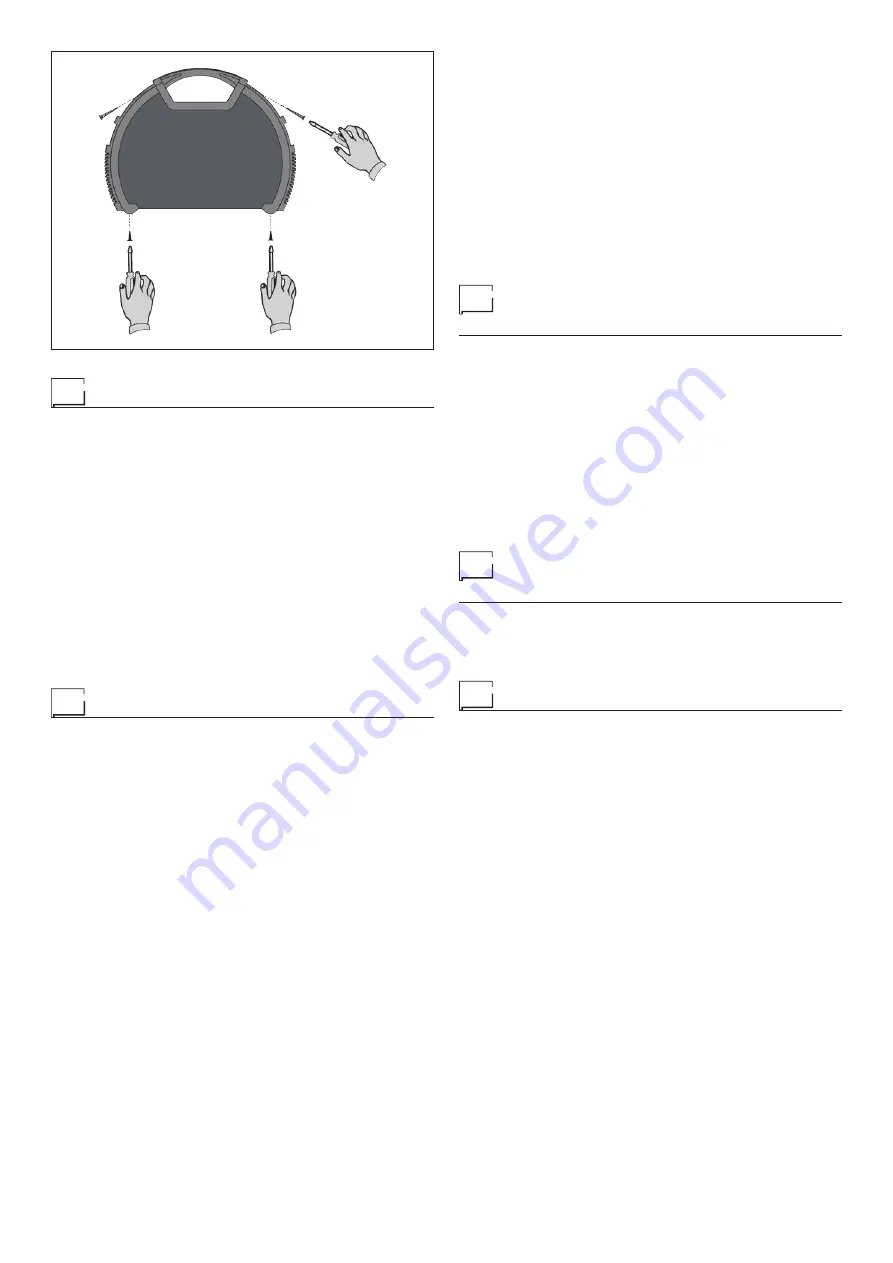
FIG. G
tive parameter. With this kind of torch, it is also possible to scroll
the saved programmes by pressing the two (+) and (-) buttons.
NOTE: The value shown on the display during welding represents
the effective current output with all types of control.
The digital control unit of the
welding power source
is fitted with a
control recognition device which allows it to identify which device
is connected and take action accordingly. To allow the command
recognition device to work correctly, connect (with the welding
power source switched off) the required accessory to the relative
connector and then switch on the welding power source with the
on/off switch.
When the welding power source is doing a programmed weld, if a
remote control command is activated (and the self-recognition pro-
cedure is carried out), it exits programming automatically.
The pointing out of any difficulties
and their elimination
The supply line is attributed with the cause of the most common
difficulties. In the case of breakdown, proceed as follows:
1) Check the value of the supply voltage
2) Check that the power cable is perfectly connected to the plug
and the supply switch
3) Check that the power fuses are not burned out or loose
4) Check whether the following are defective:
•
The switch that supplies the welding power source.
•
The plug socket in the wall.
•
The generator switch.
NOTE: Given the required technical skills necessary for the repair
of the generator, in case of breakdown we advise you to contact
skilled personnel or our technical service department.
Procedure for welder assembly
and disassembly
Proceed as follows (Fig. G):
•
Unscrew the 4 screws holding the front and back panels.
•
Unscrew the 2 screws holding the handle.
•
Proceed the other way round to re-assemble the welder.
Digital interface PCB replacement
Proceed as follows:
•
Unscrew the 4 screws fastening the front rack panel.
•
Remove the adjustment knob.
•
Extract wiring connectors from digital interface PCB.
•
Remove digital interface PCB by lifting it out of its supports.
•
Proceed vice versa to assemble new digital interface PCB.
Summary of Contents for DIX TIG GO 1406.M HF
Page 9: ...9...


