4
Hydraulic connection between the
equipment and the welding unit
With separate wire feeder
The hydraulic connection between the cooling system and the
generator must be formed using the connection cable. The de-
livery (blue coloured) and return (red coloured) water tubes,
used for cooling the torch of the welding machine, are part of
the interconnection cable and should be connected as follows:
•
Interconnection cable on generator side: connect up tubes
to their rapid couplings (blue and red coloured) at the back
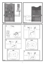
of the coolant system (Fig. C1).
With built-in wire feeder (compact)
The hydraulic connection between the cooling system and the
generator must be formed using the water-cooled torch.
The delivery (blue) and return (red) water hoses are part of the
water-cooled torch, and these are used to cool the welding set
torch and must be connected to the respective (blue and red)
quick couplings on the front of the cooling unit (Fig. C2).
Start-up / drainage
Before connecting the equipment to the utilities check the
rating plate to make sure the voltage and frequency of the
mains correspond and check that the main circuit break-
er on the equipment is turned to “O”.
Upon the first usage following a period of extended inactivity
of the device or in the case in which the electropump does not
go under pressure (slight whistle), it is necessary to undertake
drainage in order to eliminate all the air bubbles present with-
in the hydraulic circuit.
Carry out the following operations following the assembly in-
structions indicated here (Fig. D) :
A) Unscrew the tank’s cap and, using a funnel, fill it with dis-
tilled water. In case of particularly rigid climates with air
temperature near to 0° C it is necessary to add antifreeze
to the cooling distilled water. Do not use antifreeze con-
taining propylene because it could provoke blockage of
the electropump.
B) Connect the hose supplied to the blue quick coupling and
insert the other end of the hose into a receptacle that con-
tains the water.
C) Switch the welding machine on by turning the main switch
to position 1 and switch on the cooling system using the
relevant switch. Then wait about 30 seconds to allow the
cooling system to circulate the liquid.
D) Wait for the exit of the liquid. The operation will be termi-
nated when the liquid exits in a constant way and without
any traces of air bubbles.
E) Once the operation has been completed switch off the
welding machine and the cooling system.
F) Then tighten the cap on the tank again before starting work.
Maintenance
WARNING: Prior to undertaking any kind of inspection within
the machine, unplug the device from feed.
•
Periodically check the level of the cooling fluid.
•
Add fluid whenever it drops below the minimum level indi-
cated.
•
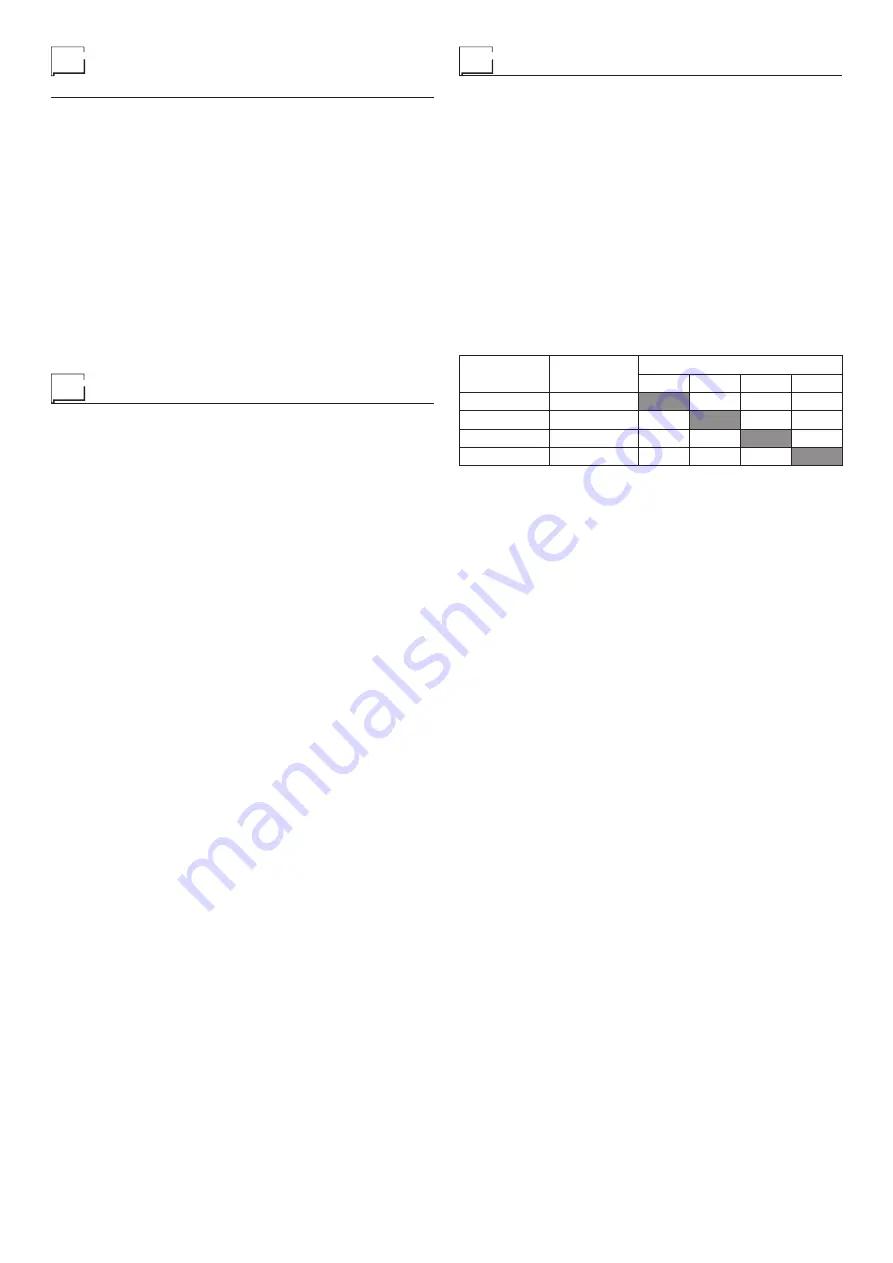
Add antifreeze when the room temperature is below 2°C (ta-
ble 2).
•
Make sure all joints are tight and that there areno leaks
•
Periodically clean the radiator with compressed air to elimi-
nate the dust that reduces the cooling capacity.
IMPORTANT: Original spare parts have been specially de-
signed for our equipment. The use of non-original spare parts
may cause variations in performance or reduce the foreseen
level of safety. We decline all responsibility for the use of non-
original spare parts.
Table 2
Distilled
water
Antifreeze
External temperature
0°C
-10°C
-15°C
-20°C
80%
20%
75%
25%
70%
30%
65%
35%
Summary of Contents for DIX CM 653.M
Page 5: ...5 FIG C1 FIG C2 FIG D...
Page 8: ......


