2
ENGLISH
EN
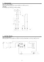
Electrical wiring of the welding cooling device
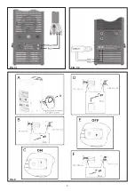
Hydraulic connection between the equipment and
the welding unit
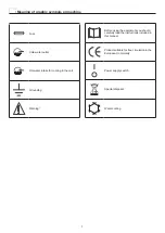
Meaning of graphic symbols on machine
Introduction
Thank you for buying our product.
In order to get the best performance out of the plant and ensure
the maximum lifespan of its parts, the use and maintenance
instructions contained in this manual must be read and strictly
complied with, as well as
the safety instructions contained
in the relevant folder
. If repairs to the plant are required, we
recommend that our clients contact our service centre work-
shops, as they have the necessary equipment and personnel
that are specifically trained and constantly updated.
All our machines and equipment are constantly developed and
so changes may be made in terms of their construction and
features.
Description
The device, particularly suited for cooling by means of water
circulation utilised in particularly heavy welding operations, is
composed in its essential parts of:
•
A single-phase electric pump.
•
A plastic tank.
•
A radiator.
•
A pressure switch.
•
A protection fuse.
The cooling module is particularly compact and lightweight. It
is designed as part of a welding power source. For other appli-
cations, please contact your DINSE consultant.
Technical data
The general technical data of the system are summarized in
table 1.
Table 1
Model
CM653.M - CM 589.M
Single-phase input
V
400
Frequency
Hz
50/60
Max power supply
kW
0,3
Max current absorbed
A
0,9
Delayed fuse
A
1,6
Coolant
20%-30% antifreeze
70%-80% distilled
water
Cooling power Φ
1
kW
0,95
Capacity with 4 m TIG torch
l/min
1,6
Capacity with 4 m MIG/MAG
torch
l/min
1,4
Capacity with 4 m MIG/MAG
torch + 10 m extension cable
l/min
1,15
Max pressure
bar
4,3
Standards
IEC 60974-2
Protection class
IP 23
Insulation class
F
Tank capacity
l
5
Dimensions
mm
670-235-305
Weight
kg
16
Weight with liquid
kg
21
Copyright © 2018 DINSE G.m.b.H., Hamburg.
These instructions or excerpts there of shall not be duplicated, transla-
ted or reproduced, nor shall they be stored, processed, transmitted or
distributed by any electronic means without the prior written permission
of DINSE G.m.b.H.
D I N S E G . m . b . H .
Tarpen 36 • D-22419 Hamburg
Tel. +49 (0)40 658 75-0
Fax +49 (0)40 658 75-200
[email protected] – www.dinse.eu
Summary of Contents for DIX CM 653.M
Page 5: ...5 FIG C1 FIG C2 FIG D...
Page 8: ......


