background image


Operations:


1

Preheat 

Preheat the PCB board and BGA chip, and the temperature of constant temperature oven is set at 

80 

  -100 

,  for  4-8  hours  to  remove  internal  moisture  of  the  PCB  and  BGA,  to  prevent  the 

burst phenomenon when heating. 

2

Remove   

Place the PCB board into the bracket on the repair station,and select the appropriate hot air reflow 
nozzle,and  set  the  appropriate  soldering  curve,press  the  open  button  until  it  finishes,and  then 
move the hot air manually,to suck the BGA chip away with the vacuum suction pen. 

3

Clean-up welding 

The  BGA  pad  clean-up  ,  one  with  de-soldering  line  to  drag  flat,  the  second  with  iron;  Best  to 
remove the tin a short time after the BGA removed , then BGA has not completely cooled , and the 
temperature  difference  make  less  damage  to  the  pad;use  the  flux  can  improve  the  activity  of 
soldering tin,better to clean the soldering tin. Particular attention not to damage the PCB pad,and 
in order to ensure the reliability of BGA solder, when the cleaning pad to make use of some of the 
solder paste residues with more volatile solvents , such as plate washer water, industrial alcohol. 

4

BGA re-balling 

Wipe the paste flux equably with the brush pen on the BGA pad, choose the right steel mesh, and 
then plant tin beads by the re-balling kit on the right pad. 

5

BGA tin beads welding 

Heat the bottom heating zone of BGA re-balling station and then weld the tin beads on the pad. 

6

Besmear flux 

Wipe  the  paste  flux  with  the  brush  pen  on  the  PCB  pad.  If  you  wipe  so  much,  it  will  cause 
connected  welding,  on  the  contrary,  it  will  cause  null  welding.  In  order  to  wipe  off  dust  and 
impurity of tin balls, and enhance welding effect, the welding paste must be wiped equally. 

7

Place the BGA chip 

Place the BGA chip on the PCB board with manual alignment and silk-screen borders, meanwhile 
the tension of the solder joint when melt will have a good self- alignment effect. 

8

Weld 

First, put the PCB board which is pasted with BGA chip on the positioning stand, and then move 
the hot wind head to the working place. Second, choose the appropriate backflow nozzle and set 
right welding temperature curve, start heating, open the switch, and then run the welding process. 
Besides, after the welding process is finished, you have to cool the BGA by the cooling fan. Hoist 
the upper hot wind head and make the bottom of hot wind nozzle apart from the surface of BGA 
3-5mm, and  stay 30-40  seconds,  or,  you  can  move the hot  wind  head after the  starting  switch  is 
put out, withdraw the hot wind head.Finally, take away the PCB board from the heating zones.  
  (1)

 null welding


Because  of  counterpoint  by  hand  will  cause  deviation  between  chip  and  welding  plate,  surface 
tension of tin ball will make BGA chip and welding plate in the process of automatic correction. 
Once  heating,  BGA  falls  not  evenly,  which  cause  the  chip  drops  not  evenly.If  stop  reflowing  at 
this time, the chip will not fall normally,which will cause the phenomenon of empty welding and 
false  welding.So  you  need  to  extent  time  of  third 

forth  temperature  zones  or  add  the  bottom 

pre-heating temperature to make ,the tin balls meltdown and drop evenly. 

Summary of Contents for DH-B1 BGA

Page 1: ...k Station Manual ADD 3rd floor 46th building Da Yangtian Industry District Shajing Town Bao an District Shenzhen China Website www sinobga com Tel 86 755 29091633 29091833 Fax 86 55 29091622 E mail dh...

Page 2: ...had expanded into industries like individual repair factories education military and aerospace etc And we had established the point of sales and end service at locally and abroad Your satisfaction is...

Page 3: ...ire or electric shock 7 Electrical box has the high voltage components do not attempt to disassemble 8 If the metal objects or liquids fall into the repair station when it works immediately disconnect...

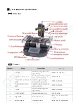
Page 4: ...back adjustment handle Adjust the upper heating of Forward and back position Rotating the handle 4 Up and down adjustment handle Adjust the upper heating of up and down position Rotating the handle 5...

Page 5: ...connect temperature line 17 IR preheating zone BGA rework with warm up 18 PCB support Move the right position clamping the PCB 19 Universal fixture Adjust the PCB in any direction 20 Powerful cross fa...

Page 6: ...temperature time angle cooling and vacuuming can all be set on the interface 7 There are 6 8 levels of variable and constant temperature controls Massive storage of temperature curves which are Insta...

Page 7: ...pen on the PCB pad If you wipe so much it will cause connected welding on the contrary it will cause null welding In order to wipe off dust and impurity of tin balls and enhance welding effect the we...

Page 8: ...ircuit phenomenon when reflows the chips fall entirely on the PCB pads the so we need to appropriately reduce the heating section of the third and fourth soldering temperature and time or reduce the b...

Page 9: ...of touch screen operation 1 Switch on the power the BGA rework station can connect with electricity The home page of touch screen will appear the interface like the following picture and then you can...

Page 10: ...10 2 When we choose English it will appear the working interface like the following picture 3 Input password then click to enter...

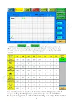
Page 11: ...cross flow cooling fan 6 Vacuum Switch button of the vacuum pen Manual control of the vacuum pen 7 Screen shot Store the currant curve to the USB drive 8 Heating time Total heating time 9 Curve name c...

Page 12: ...stant temperature time and the speed of heating the speed of heating with SEC calculation Three zone temperatures can be set 8 levels of variable and constant temperature controls If need you can chan...

Page 13: ...machine can be mass storage temperature curve User can store a a variety of manufacturing process parameters in the system when replacing of the production process direct call to the parameters saved...

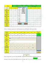
Page 14: ...w parameter click the parameter you will get the following interface Input the parameter you need press ENTER key When temperature parameters Settings of these three temperature zones are finished cli...

Page 15: ...flashing showing the machine entering the temperature kept status and the whole heating temperature will keep the current temperature constant working until click the button again it will return to n...

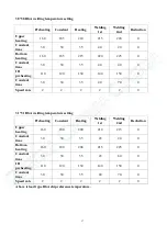
Page 16: ...t can recover to normal state usual temperature parameters as follows Lead temperature curve welding 41 41 BGA welding temperature setting Preheating Constant Heating Welding 1st Welding 2nd Reduction...

Page 17: ...0 20 0 Bottom heating 160 185 215 220 225 0 Constant time 30 30 35 40 40 0 IR preheating 110 120 130 140 150 0 Constant time 30 30 35 40 70 0 Speed rate 2 2 2 2 2 0 Preheating Constant Heating Welding...

Page 18: ...heating 165 190 225 245 255 240 Constant time 30 30 35 55 25 15 IR preheating 110 120 130 140 150 160 Constant time 30 30 35 40 40 70 Speed rate 2 2 2 2 2 2 Preheating Constant Heating Welding 1st We...

Page 19: ...cuum pen and then remove the PCB board from the positioning frame 4 When welding the BGA chip set the cooling fan to manual grade close vacuum After the temperature curve runs to the end the buzzer wi...

Page 20: ...ality and shorten the using time of infrared heating element If the heating element was burn out because of these our company is not responsible for free change Concluding remarks In the electric prod...

Page 21: ...A rework station DH B1 SET 1 Vacuum pen PCS 1 2 Vacuum sucker PCS 3 3 Instruction manual DH B1 COPY 1 4 Hot air nozzle 31 31 38 38 41 4 1 55 55 34 34 PCS 5 5 Universal fixture PCS 6 6 Plum knob PCS 6...

Reviews:

Related manuals for DH-B1 BGA