7
©
Dinel, s.r.o. HLM–35
6 . m
echanical
mounting
•
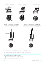
Installation by screwing into the wall of the vessel of the measured area.
•
When using the cable containing the equalising capillary, it is necessary to use a non-
hermetic connection box for connection to connecting cables.
•
For CK and SK type level meter, when winding up excess cable into rolls, a diameter of
min. 30 cm must be maintained. We do not recommend shortening or otherwise me
-
chanically adjusting the cable.
•
In tanks, where swirling of the liquids occurs as a result of strong inflow or mixing, it is
necessary to place the probe in a stilling pipe, behind a partition or at least as faw away
as possible from the source of the swirling.
•
When using it for liquids other than water, it is necessary to make a correction to the
output voltage respecting the density of the measured liquid, and if necessary consult
the application with the manufacturer.
7 . e
lectrical
connection
Electrical connection can only be made in a voltage-free state!
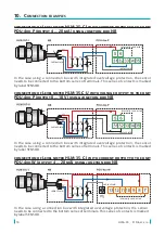
In the event that the level meter is fitted with a shielded cable, it is necessary to ground
the cable on the side of the power source for the event of a possible lightning electrical
discharge in the vicinity of the sensor.
In the event that the level meter is installed in an outdoor environment at a distance
greater than 20 m from the outdoor switchboard, or from an enclosed building, it is
necessary to supplement the electrical cable leading to the level meter with suitable
overvoltage protection.
In case of strong ambient electromagnetic interference, paralleling of conductors with
power distribution, or for distribution to distances over 30m, we recommend using a
shielded cable and its grounding on the side of the power source.
Level meters HLM-35 with a type A, B, V or H cable terminal, are connected to the assess
-
ment units permanently by a connection cable, see pg. 2.
Level meters HLM-35 with connection method type C (see pg. 2) are connected to assess
-
ing units by means of a connector socket with a press-in cable, or by means of a detach
-
able connector socket without a cable (see accessories), the connector is not part of the
sensor. In this case the cable is connected to the inside pins of the socket according to the
figure below.
Inside view of the connector
socket (variant "C")
U
out
(BK)
0 V (BU)
+U (BR)


