


11
WARNING:
Ensure wires do not come in contact with
moving parts by securing wires in wiring tie wraps.
POWER SUPPLY REPLACEMENT
Tools Required:
Philips head screwdriver
Flat Head Screwdriver
WARNING:
If the firebox was operating prior to servic
-
ing, allow at least 10 minutes for the heating elements to
cool off to avoid accidental burning of skin.
WARNING:
Disconnect power before attempting any
maintenance to reduce the risk of electric shock or damage
to persons.
1. Remove the front glass or any accessories that are
around the fireplace and will inhibit your ability to fully
access the unit.
2. Slide the log set assembly forward and lift the log set
assembly and the ember mat out. (Figure 3)
!
NOTE:
The log set assembly has a wire attached to
the unit which can be temporarily disconnected for easier
access.
3.
On either side of the firebox gently remove the brick
panels by placing you finger in the gap and pulling
forward. The brick panels are held in place by magnets
and need minimal force to be removed.
4.
Locate the two brackets securing the flame panel in the
unit at the bottom and remove the 4 screws. (Figure 3)
5.
Gently lift the flame panel out, set aside in a safe loca
-
tion.
6. Remove the 2 hex head screws on either side of the
controls and the 4 hex head screws along each side
of the panel and gently lower the internal assembly.
(Figure 4)
7. Disconnect the two main wire connectors - one on each
side of the unit.
8. Disconnect the hanging straps at the front, ensuring
that you support the entire assembly, and lift the back
of the assembly up and off of the hook at the back. At
this point you should be able to gently set the assembly
on the surface infront of the unit to easily replace the
main control board.
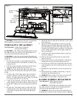
9. Locate the power supply located below the main con-
trol board. (Figure 4)
10. Remove the 4 screws that secure the main control
board to the unit.
11. Remove the 4 screws on the assembly to release the
bracket that secures the power supply to the unit.
12. Trace the wires to the main control board and the wire
nuts and replace the old connections with the new con-
nections.
13. Reinstall the support bracket over the new power sup-
ply.
14.
Re-assemble the remainder of the firebox in reverse
order from the instructions above.
WARNING:
Ensure wires do not come in contact with
moving parts by securing wires in wiring tie wraps.
BLOWER ASSEMBLY REPLACEMENT
Tools Required:
Philips head screwdriver
Flat Head Screwdriver
WARNING:
If the firebox was operating prior to servic
-
ing, allow at least 10 minutes for the heating elements to
cool off to avoid accidental burning of skin.
WARNING:
Disconnect power before attempting any
maintenance to reduce the risk of electric shock or damage
Figure 4
Main Control
Board
Power
Supply
Cutout
Element
Blower
Assembly
Hex Head
Screws
Thermistor
Main Control
Assembly
Top Front Lights
Summary of Contents for Revillusion RBF30
Page 7: ...7 WIRING DIAGRAM M M ...


