


7
PREPARATION FOR SERVICE
CAUTION:
If unit was operating prior to servicing allow
at least 10 minutes for lights, heating elements and top
panel to cool off to avoid accidental burning of skin.
Remove the firebox out of the cabinet or wall frame that
1.
surrounds the unit.
Disconnect power before attempting any maintenance.
2.
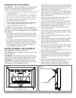
Remove the front glass assembly as shown in Figure 3
3.
Remove the screws on the back panel, which mount
4.
the fireplace to the wall. (Figure 4)
Lift the fireplace off the wall-mounting bracket, which is
5.
secured to the wall behind the fireplace. (Figure 5)
Lay the fireplace down on it’s front.
6.
!
NOTE:
If your work surface is finished and prone to
scratches (i.e. hardwood flooring), it is recommended that a
protective barrier be used underneath (i.e. cloth, cardboard,
thick plastic).
Remove the fireplace from the front trim by removing
7.
the 8 screws, which secure the firebox chassis to the
front frame: 4 Top edge; 4 Bottom edge; 4 Left edge; 4
Right edge.
Remove the 2 perpendicular screws, which secure
8.
the switch housing cover to the back panel. (With the
switches on your left side, closest to you; you will find
the screws approximately 10” inches in towards the
center, starting from the lower left).
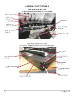
HEATER ASSEMBLY REPLACEMENT
Tools Required:
Philips head screwdriver
CAUTION:
Follow “Preparation for Service” instructions
before proceeding.
WARNING:
If the fireplace was operating prior to ser
-
vicing allow at least 10 minutes for light bulbs and heating
elements to cool off to avoid accidental burning of skin.
WARNING:
Unplug or disconnect power at the circuit
breaker before attempting any maintenance to reduce the
risk of electric shock or damage to persons
Remove the screws, which secure the heater assembly
1.
to the back panel. 4 Smaller screws secure the mount-
ing bracket in the lower center of the back panel – 2 on
left bracket and 2 on right bracket.
Remove the 4 screws, which secure the heater assem-
2.
bly housing cover to the back panel. The can be found
on the back panel; to the right and the top of the right
side mounting bracket.
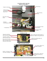
Carefully turn the fireplace back over, onto it’s back
1.
with the switches and bottom closest to you.
Locate the switch-housing cover on the lower, interior
2.
right side. Remove the 2 screws, which secure the
upper housing cover, just below the flame motor, to the
electrical/switch-housing cover beneath it.
Remove 3 screws which secure the switch housing
3.
from the bottom panel
Remove the (1) screw, which secures the switch hous
-
4.
ing from the lower part of the side panel, and (1) on the
bottom, front right corner.
Remove the switch housing cover out of the chassis
5.
and set it aside.
Remove the 8 screws from the bottom panel surround-
6.
ing the vent area, which secure the heater assembly
housing cover and deflector. (2) to the right; (4) to the
left; (2) closest to the front face.
Remove the 3 screws, which secure the heater assem-
7.
bly housing cover to the heater assembly. (2) – Right;
(1) – Left on the slats covering the fan.
Remove the 4 screws on the deflector vent cover - (2)
8.
screws Left; (2) screws Right.
Remove the (2) heater assembly mounting brackets off
9.
the rear left and the right of the blower motor and fan.
Each bracket has 2 screws securing it to the blower
assembly.
Attach the mounting brackets to the new heater assem-
10.
bly in the same location as the original heater.
Remove the wire connections on the original blower
11.
motor and elements noting their original locations.
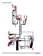
Panel Mounting Holes
Figure 4
Wall Bracket Supports
Wall Bracket
Figure 5


