


10
www.dimplex.com
THERMOSTAT REPLACEMENT
Tools Required:
Phillips Head Screwdriver
Needle Nose Pliers
CAUTION:
Follow “Preparation for Service” instructions
before proceeding.
WARNING:
If the fireplace was operating prior to ser
-
vicing allow at least 10 minutes for light bulbs and heating
elements to cool off to avoid accidental burning of skin.
WARNING:
Unplug or disconnect power at the circuit
breaker before attempting any maintenance to reduce the
risk of electric shock or damage to persons.
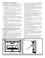
Carefully turn the fireplace back over, onto it’s back
1.
with the switches and bottom closest to you.
Locate the switch-housing cover on the lower, interior
2.
right side. Remove the 2 screws, which secure the
upper housing cover, just below the flame motor, to the
electrical/switch-housing cover beneath it.
Remove 3 screws which secure the switch housing
3.
from the bottom panel
Remove (1) screw, which secures the switch housing
4.
from the lower part of the side panel, and (1) on the
bottom, front right corner.
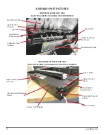
Remove the switch housing cover out of the chassis
5.
and set it aside.
Remove the dial off the control shaft by pulling forward
6.
away from the thermostat.
!
NOTE:
Note that the dial will only go back on the shaft
one way when replacing.
Remove thermostat from the mounting bracket by re-
7.
moving the 2 Philips screws located on the bracket.
Taking note of the original location of each wire con-
8.
nected to the thermostat remove the wires and place
onto the new thermostat.
!
NOTE:
Using a flat head screwdriver gently pry
between the end of the connector and the thermostat to
release the wires.
Re-assemble in reverse order as described above.
9.
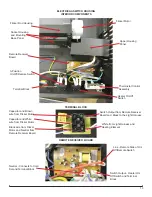
REMOTE RECEIVER BOARD
REPLACEMENT
Tools Required:
Phillips Head Screwdriver
Needle Nose Pliers
CAUTION:
Follow “Preparation for Service” instructions
before proceeding.
WARNING:
If the fireplace was operating prior to ser
-
vicing allow at least 10 minutes for light bulbs and heating
elements to cool off to avoid accidental burning of skin.
WARNING:
Unplug or disconnect power at the circuit
breaker before attempting any maintenance to reduce the
risk of electric shock or damage to persons.
Carefully turn the fireplace back over, onto it’s back
1.
with the switches and bottom closest to you.
Locate the switch-housing cover on the lower, interior
2.
right side. Remove the 2 screws, which secure the
upper housing cover, just below the flame motor, to the
electrical/switch-housing cover beneath it.
Remove 3 screws which secure the switch housing
3.
from the bottom panel
Remove (1) screw, which secures the switch housing
4.
from the lower part of the side panel, and (1) on the
bottom, front right corner.
Remove the switch housing cover out of the chassis
5.
and set it aside.
Taking note of the original location of each wire con-
6.
nected to the board, remove each wire and connect
them onto the same location on the new receiver
board.
!
NOTE:
Using a flat head screwdriver gently pry
between the end of the connector and the circuit board to
release the wires.
Remove the old board off the plastic mounts, by
7.
squeezing the tab inward and sliding the board off.
Replace any plastic mounts that may have broken by
8.
pushing the old mounts out towards the back. Replace
the new mounts from the back.
Line up the holes on the corners of the new remote re-
9.
ceiver board and press the new board onto the mounts.
Make sure the board is secure.
Re-assemble in reverse order as described above.
10.
POWER CORD REPLACEMENT
Tools Required:
Phillips Head Screwdriver
Needle Nose Pliers
CAUTION:
Follow “Preparation for Service” instructions
before proceeding.
WARNING:
If the fireplace was operating prior to ser
-
vicing allow at least 10 minutes for light bulbs and heating
elements to cool off to avoid accidental burning of skin.
WARNING:
Unplug or disconnect power at the circuit
breaker before attempting any maintenance to reduce the
risk of electric shock or damage to persons.
Carefully turn the fireplace back over, onto it’s back
1.
with the switches and bottom closest to you.
Locate the switch-housing cover on the lower, interior
2.
right side. Remove the 2 screws, which secure the
upper housing cover, just below the flame motor, to the
electrical/switch-housing cover beneath it.
Remove 3 screws which secure the switch housing
3.
from the bottom panel
Remove (1) screw, which secures the switch housing
4.
from the lower part of the side panel, and (1) on the
bottom, front right corner.
Remove the switch housing cover out of the chassis
5.
and set it aside.
Unscrew the 2 wire connectors that join the power cord
6.
at the bottom to the wire leads coming down from the
top.


