


11
PARTIALLY REFLECTIVE GLASS
REPLACEMENT
Tools Required:
Phillips Head Screwdriver
WARNING:
If the fireplace was operating prior to ser-
vicing, allow at least 10 minutes for light bulbs and heating
elements to cool off to avoid accidental burning of skin.
WARNING:
Disconnect power before attempting any
maintenance to reduce the risk of electric shock or damage
to persons.
1. Carefully remove the loose media from the front tray, if
applicable.
2. Wall Mount:
Remove the fireplace assembly from the
wall by carefully lifting it upward, releasing it from the
flanges of the wall-mounting bracket. .
Pedestal Mount:
Carefully lay the unit face down on
a flat surface and remove the six screws holding the
pedestal to the unit.
3. Carefully set the unit upright on a flat working surface.
!
NOTE:
If necessary, lay a protective barrier between
the unit and your work surface, (i.e. cloth, cardboard, thick
plastic) to avoid scratching your work surface.
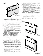
4. Remove the ten screws around the outside flange of
the end panel. (Figure 6)
5. Remove the eight screws on the end panel. (Figure 7)
6. Gently open the end panel, being careful not to strain
the wires connected to the switches
7. Remove the partially reflective glass by sliding it out of
the unit.
8. Reassemble in the reverse order as above.
LED LIGHT ASSEMBLY REPLACEMENT
Tools Required:
Phillips Head Screwdriver
WARNING:
If the fireplace was operating prior to ser-
vicing, allow at least 10 minutes for light bulbs and heating
elements to cool off to avoid accidental burning of skin.
WARNING:
Disconnect power before attempting any
maintenance to reduce the risk of electric shock or damage
to persons.
1. Carefully remove the loose media from the front tray, if
applicable.
2. Wall Mount:
Remove the fireplace assembly from the
wall by carefully lifting it upward, releasing it from the
flanges of the wall-mounting bracket. .
Pedestal Mount:
Carefully lay the unit face down on
a flat surface and remove the six screws holding the
pedestal to the unit.
3. Carefully lay the unit on a flat working surface, with the
opening facing up.
!
NOTE:
If necessary, lay a protective barrier between
the unit and your work surface, (i.e. cloth, cardboard, thick
plastic) to avoid scratching your work surface.
4. Remove the ten screws around the outside flange of
the end panel. (Figure 6)
5. Remove the eight screws on the end panel. (Figure 7)
6. Gently open the end panel, being careful not to strain
the wires connected to the switches
7. Remove the partially reflective glass by sliding it out of
the unit.
8. Locate the three securing screws for the LED light as-
sembly along the bottom and remove the light assem-
bly. (Figure 8)
9. Disconnect the wiring connections noting their original
location.
10. Properly orient and install the new LED lights and con-
nect all of the wiring.
11. Reassemble in the reverse order as above.
FLICKER MOTOR & FLICKER ROD
REPLACEMENT
Tools Required:
Phillips Head Screwdriver
WARNING:
If the fireplace was operating prior to ser-
vicing, allow at least 10 minutes for light bulbs and heating
elements to cool off to avoid accidental burning of skin.
WARNING:
Disconnect power before attempting any
maintenance to reduce the risk of electric shock or damage
to persons.
1. Carefully remove the loose media from the front tray, if
applicable.
2. Wall Mount:
Remove the fireplace assembly from the
wall by carefully lifting it upward, releasing it from the
flanges of the wall-mounting bracket. .
Pedestal Mount:
Carefully lay the unit face down on
a flat surface and remove the six screws holding the
pedestal to the unit.
3. Carefully lay the unit on a flat working surface, with the
opening facing up.
!
NOTE:
If necessary, lay a protective barrier between
LED Lights
Figure 8


