Dimplex DF2690 Owner'S Manual Download Page 15


15

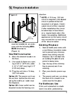
1.  Slide fireplace out of mantel. 
2.  Lay unit on it’s back for safe 

removal of front glass.

3.  Remove four Phillips screws 

from the right side of trim.

4. 

Slide glass to right side of 

fireplace to remove (Figure 

7).

5. 

Pull the front edge of the 

plastic ember bed or plastic 

grate up and forward until the 

rear tab releases from the 

ledge located at the bottom 

of the partially reflective glass 

(Figure 8).

6.  Remove flicker rod by slid

-

ing flicker rod to the left away 

from the flicker motor and 

lifting out.

7.  Remove light bracket for 

easier access to light bulbs.

!

 IMPORTANT: 

Only handle the 

log set by the ember bed.

!

 NOTE: 

Log set fits tightly into 

firebox, some force may be nec

-

essary to remove.
8.  Set log set in front of fire

-

place.

9.  Unscrew bulbs counter clock

-

wise.

10. Insert new bulbs.

 Maintenance

11.  Replace the log set by insert

-

ing the front edge of the 

fireplace and push down on 

the rear edge of the ember 

bed until it snaps into place 

(Figure 8).

12. Lay unit on it’s back and slide 

front glass back into position 

and attach


trim.

!


NOTE: 

Ensure the log set is 

installed tightly under the back 

ledge to prevent light leakage.

Upper Light Bulb Requirements

Quantity of two clear chandelier 

or candelabra bulbs with an E-12 

(small) socket base, 15 Watt rat

-

ing. 

Do not exceed 15 Watts per 

bulb.
To access the upper light bulb 

area:

 CAUTION: 

Allow at least five 

minutes for the light bulbs to cool 

before touching them to avoid ac

-

cidental burning of the skin. 
1.  Slide fireplace out of mantel.
2.  Lay unit on it’s back for safe 

removal of front glass.

3.  Remove four Phillips screws 

from right side of trim.

4.  Remove trim.
5. 

Slide glass to the right side of 

Summary of Contents for DF2690

Page 1: ...read this manual first before attempting to install or use this fireplace For your safety always comply with all warnings and safety instructions contained in this manual to prevent personal injury o...

Page 2: ...emphasize CAUTION Procedures and techniques which if not carefully followed will result in damage to the equipment WARNING Procedures and techniques which if not carefully followed will expose the us...

Page 3: ...l void the warranty Please record your model and serial numbers below for future reference model and serial numbers can be found on the Model and Serial Number Label of your fireplace NO NEED TO RETUR...

Page 4: ...te any unit with a damaged cord or plug or if the heater has malfunctioned or if the electric fireplace has been dropped or damaged in any man ner contact Dimplex Technical Service at 1 888 346 7539 D...

Page 5: ...ified electri cian should new circuits or outlets be required Always use properly ground ed fused and polarized outlets Disconnect all power supply before performing any cleaning maintenance or reloca...

Page 6: ...ause harmful interference to radio or television reception which can be determined by turning the equipment off and on the user is encouraged to try to correct the interference by one or more of the f...

Page 7: ...NING To reduce the risk of fire do not store or use gaso line or other flammable vapors or liquids in the vicinity of the heater CAUTION Clearance for air circulation beneath the fire place insert is...

Page 8: ...ire place Figure 3 3 Remove the front glass if necessary 4 Remove the foam block from within the fireplace Figure 2 5 Using side cutters or scissors cut and remove the two cable ties as shown in Figur...

Page 9: ...cuit is preferred but not essential in all cases A dedi cated circuit will be required if after installation the circuit breaker trips or fuse blows on a regular basis when the heater is operating Add...

Page 10: ...er from entering unit This must be installed away from showers tubs etc Never locate fireplace where it may fall into a bathtub or other water con tainer High temperatures may be generated under certa...

Page 11: ...ure to your individual requirements turn the Figure 5 thermostat control clockwise all the way to turn on the heater When the room reaches the desired temperature turn the thermostat knob counter cloc...

Page 12: ...y through the three lev els of the fireplace Level 1 The flame effect is turned on and the first red indica tor light flashes momentarily Level 2 The flame effect remains on the heater is activated to...

Page 13: ...independent frequen cies to prevent interference with other units NOTE Before attempting any operation with the remote control pull the plastic insulator strip out from between the remote casing and b...

Page 14: ...flames and embers and two bulbs above the log that illuminate the log exterior Helpful Hints It is a good idea to replace all light bulbs at one time if they are close to the end of their rated life G...

Page 15: ...place 9 Unscrew bulbs counter clock wise 10 Insert new bulbs Maintenance 11 Replace the log set by insert ing the front edge of the fireplace and push down on the rear edge of the ember bed until it s...

Page 16: ...aintenance Glass Cleaning The glass is cleaned in the factory during the assembly operation During shipment installation handling etc the glass may col lect dust particles these can be removed by dust...

Page 17: ...n material and workmanship for a period of 2 years from the date of the first purchase of such products as follows a a repair or replacement warranty on defec tive products or parts including in home...

Page 18: ...ted warranty entitles the purchaser to on site or in home warranty services Accord ingly Dimplex will be responsible for all labour and transportation costs associ ated with the repair or replacement...

Page 19: ...not responsible for IN NO EVENT WILL DIMPLEX OR ITS DIRECTORS OFFICERS OR AGENTS BE LIABLE TO THE PURCHASER OR ANY THIRD PARTY WHETHER IN CON TRACT IN TORT OR ON ANY OTHER BASIS FOR ANY INDIRECT SPEC...

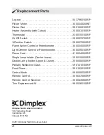
Page 20: ...t 2300150100RP On Off Switch 2800070700RP 3 Position Switch 2800070500RP Flame Action Control w Potentiometer 3000240500RP Light Dimmer Control w Potentiometer 3000250100RP Power Cord 4100040200RP Sin...

Reviews: