background image


4

ASSEMBLY & OPERATION 

If your fan comes ready assembled ignore this section. 
 
Assembly of your pedestal fan 

1.


Separate the front and rear guard if they are connected. 

2.


Remove the four position screws on the motor, offer up and align 

the rear guard with the four holes on the motor (handle to top of the 
fan) insert the four position screws and tighten. 

3.


Loosen the set screw on the blade, slide the blade into the shaft of 
the motor, and tighten the set screw onto the flat of the shaft to 
secure the blade. Ensure that the blade does not foul the guards. 

4.


Assemble the front guard to the rear guard. Tighten the screw and 
nut, and secure the retaining slips. 

5.


Loosen the set screws on the base plate with the spanner provided. 
Attach the pole and re-tighten the screws back onto the base plate. 

 
Operation of your pedestal fan 
The power switch is incorporated in the speed control switch on top of the 

fan. 
0 – The fan is switched off. 
1 – The fan operates at the lowest speed. 
2 – The fan operates at medium speed. 
3 – The fan operates at the highest speed. 
 
To blow air in one direction and stop oscillation, allow the fan to move into 
the desired position and pull the clutch knob up. Press the clutch knob down 
to return to a normal oscillation function. 

Summary of Contents for DCPF40

Page 1: ...40cm HV PEDESTAL FAN Model DCPF40 INSTRUCTION MANUAL PLEASE READ THE INSTRUCTION MANUAL CAREFULLY BEFORE USING THE UNIT...

Page 2: ...2 TABLE OF CONTENTS IMPORTANT INFORMATION 1 STRUCTURE 3 ASSEMBLY OPERATION 4 CLEANING MAINTENANCE 5 TECHNICAL SPECIFICATIONS 7 WARRANTY 7...

Page 3: ...ever share the power outlet with other appliances Never connect or disconnect the power plug with wet hands to avoid electric shocks Never put rods or objects into the opening of the unit Never use an...

Page 4: ...s or upside down while transporting Place the unit on a flat surface with less than 5 degree inclination To avoid damaging the unit do not use chemical solvents i e Benzene alcohol grazer or harsh cle...

Page 5: ...3 Blade 4 Position screw 5 Rear guard 6 Nut 7 Set screw 8 Power switch 9 Oscillation knob 10 Motor 11 Power cord 12 Tube 13 Cover ring 14 Joint screw 15 Spring washer 16 Spring 17 Base plate 18 Sprin...

Page 6: ...blade does not foul the guards 4 Assemble the front guard to the rear guard Tighten the screw and nut and secure the retaining slips 5 Loosen the set screws on the base plate with the spanner provide...

Page 7: ...erse in water for cleaning never allow water to drip into the motor housing 6 In the off season it is important to keep your unit in a safe dry location Please remember to protect the unit from dust o...

Page 8: ...fficiency decreases the unit is broken or other problems arise please stop running the unit and unplug it Ask for advice by calling your local after sales service agent or the Customer Care Centre on...

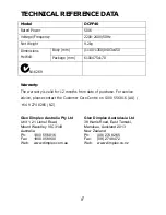
Page 9: ...12 months from date of purchase For service advice please contact the Customer Care Centre on 1300 556 816 AU 64 9 274 8265 NZ Glen Dimplex Australia Pty Ltd Glen Dimplex Australasia Ltd Unit 1 21 Lio...

Reviews: