


4 www.dimplex.com
MAINTENANCE
WARNING:
Disconnect power before attempting any
maintenance or cleaning to reduce the risk of fire, elec-
tric shock or damage to persons.
Filling the water tank
When the water tank is empty, the flame effect shuts off
and you will hear 2 audible beeps, follow these steps.
CAUTION:
Allow at least five minutes for components to
cool before disassembling the unit to refill.
1. Gently remove the top tray and place it carefully on the
ground.
2. Turn the On/Off switch to the off position
(0)
(Figure 1A)
3. Remove the refill container by lifting upwards and out-
wards.
4. Refill the container with tap water.
!
NOTE:
Normal tap water can be used in the Optimyst
®
as long as the tap water is not considered to be hard water.
In the event your tap water is hard, you may use softened
water or distilled water with ⅛ tsp. of salt (0.5 mL) added to
the water reservoir. (The use of additional salt should only
be when you notice that the unit is not producing mist as
expected.)
5. Screw the cap back on,
do not overtighten
.
6. Return the refill container to the sump, with the tank cap
facing down and the flat side of the tank facing outward.
7. Turn the On/Off switch to the off position
(I) .
(Figure 1A)
8. Gently place the top tray back into position.
If you do not intend on using the unit for longer than 2
weeks, empty and drain the unit of water, and dry all of the
water containing components.
Transducer Replacement
After prolonged usage the ability for the unit to produce
mist may become reduced. When this occurs the replace-
ment of the transducer may be required. This unit comes
with 2 additional transducers, located behind the right mod-
ule, which can installed when this occurs.
!
NOTE:
There is a small tab that holds the transducer in
place, that needs to be released before it can be removed.
Cleaning
It is recommended that the top cover assembly, sump and
transducer are cleaned with soap and water on a
biweekly
basis.
CAUTION:
Do not put plastic components in the dish-
washer.
Filter Cleaning
The air filters can be removed and gently rinsed with water
to clean and dried on a towel before reinstalling.
!
NOTE:
Replace the filter so that the course black filter is
facing the back of the unit.
Surface Cleaning
Use a warm damp cloth only to clean surfaces of the unit.
Do not use abrasive cleaners.
!
NOTE:
If you need to move the unit ensure that all of
the components that contain water have been emptied be-
fore relocating.
Servicing
Except for installation and cleaning described in this manu-
al, an authorized service representative should perform any
other servicing.
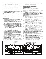
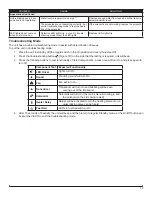
Figure 3
!
NOTE:
It is possible to synchronize up to 5 units to one
remote control.
Battery Replacement
To replace the battery:
1. Slide battery cover open on the remote control (Figure
3).
2. Install two 1.5 Volt (AAA) battery in the battery holder.
3. Close the battery cover.
Battery must be recycled or disposed of properly.
Check with your Local Authority or Retailer for recy-
cling advice in your area.
Battery Cover
Figure 4
Sump
Top Cover
Assembly
Release Tabs


