Dimplex 690932 Series Owner'S Manual Download Page 8

8  

www.dimplex.com

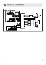
  Fireplace Installation

Option #1

 - The power cord can 

be lead from behind the trim 

and along the wall to an outlet 

near the fireplace. 

Option #2

 - A new outlet can be 

installed inside the new frame 

construction.  Plug the unit into 

a 15 Amp/120 Volt outlet.  

!

 NOTE:  

A 15 Amp, 120 Volt 

circuit is required.  A dedicated 

circuit is preferred but not es

-

sential in all cases.  A dedi

-

cated circuit will be required 

if, after installation, the circuit 

breaker trips or fuse blows 

on a regular basis when the 

heater is operating.  Additional 

appliances on the same circuit 

may exceed the current rating 

of the circuit breaker.

Bathroom Installation

This firebox must be protected by 

a GFI receptacle or circuit.  If a 

receptacle is used it must be readily 

accessible.
To prevent electrical shock this unit  

is an electrical appliance that is not 

watertight and must be installed as to 

prevent water from entering the unit.  

This unit must be installed away from 

showers, tubs, etc.  Never locate fire

-

place where it may fall into a bathtub 

or other water containers.
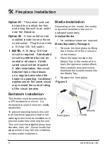
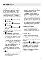
Figure 3

Front glass

Mounts

Hooks

Media Installation

Depending on the model, the media 

may come installed in the unit or 

packaged seperately.

Installed Media

•  No additional steps are required.

Media Seperately Packaged

1.  Remove the front glass by lifting 

the 2 hooks off of the 2 mounts 

on the firebox.

2.  Place the large media in the 

Media Tray in the center at the 

back (for optimum media effect), 

then carefully pour and evenly 

distribute the smaller media into 

the Media Tray.

3.  Replace the front glass.

Summary of Contents for 690932 Series

Page 1: ...ays read this manual first before attempting to install or use this fireplace For your safety always comply with all warnings and safety instructions contained in this manual to prevent person al inju...

Page 2: ...emphasize CAUTION Procedures and techniques which if not carefully followed will result in damage to the equipment WARNING Procedures and techniques which if not carefully followed will expose the us...

Page 3: ...er Manufacturer s Warranty Contact us at www dimplex com customer_support For Troubleshooting and Technical Support OR Toll Free 1 888 DIMPLEX 1 888 346 7539 Monday to Friday 8 00 a m to 4 30 p m EST...

Page 4: ...Do not run the cord under carpet ing Do not cover cord with throw rugs runners or the like Arrange IMPORTANT INSTRUCTIONS cord away from traffic area and where it will not be tripped over To disconnec...

Page 5: ...nsporting or storing the unit and cord keep in a dry place free from excessive vibration and store so as to avoid damage WARNING Remote control contains a small battery Keep away from children If swal...

Page 6: ...d malfunction or break down grounding provides a path of least resistance for electric current to reduce the risk of electric shock This product is equipped with a cord having an equipment grounding c...

Page 7: ...e man tel so that it is a minimum of in 10 mm off of the wall to ensure adequate air flow IMPORTANT If not using a Dimplex mantel the fireplace must be installed in an enclosure with the following min...

Page 8: ...y a GFI receptacle or circuit If a receptacle is used it must be readily accessible To prevent electrical shock this unit is an electrical appliance that is not watertight and must be installed as to...

Page 9: ...RD NTC TOP LIGHT ASSY FLAME LED LIGHT ASSEMBLY 1W TOP LIGHT ASSY FLICKER MOTOR HEATER ASSEMBLY MEDIA LED LIGHT ASSEMBLY LOGSET JUNCTION BOARD THERMAL CUT OUT OR POWER SUPPLY RELAY BOARD OR OR FLAME BE...

Page 10: ...g your hand vertically approxi mately 4 in 102 mm in front of the gWaveTM sensor in the upper right hand corner of the unit the unit and different control functions can be activated This is also indic...

Page 11: ...effect On or Off Activated by pressing the cor responding button on the remote or waving in front of the gWa veTM Operation When On the flame effect is vis ible in the unit 3 Heat On Off Turns the hea...

Page 12: ...ing will toggle between C and F 6 Eco Runs the heater in a reduced wattage range when activated Adjusted by pressing the cor responding button on the remote when the heater is on Indicated by the icon...

Page 13: ...urns the unit off after a preset duration from 30 minutes 0 5h to 8 hours in hour increments Activated and adjusted by re peatedly pressing the correspond ing button on the remote Indicated by the Flo...

Page 14: ...lf During this pro cess you will hear repeated beeps and the display may turn on and off CAUTION If you need to continu ously reset the heater disconnect power and call Dimplex customer service at 1 8...

Page 15: ...hipment installation handling etc the front glass may collect dust particles these can be removed by dusting lightly with a clean dry cloth To remove fingerprints or other marks the glass can be clean...

Page 16: ...r to shipment and subject to the provisions of this warranty Dimplex warrants such products to be free from defects in material and workmanship for a period of 1 year from the date of the first purcha...

Page 17: ...Y WHETHER IN CONTRACT IN TORT OR ON ANY OTHER BASIS FOR ANY INDIRECT SPECIAL PUNITIVE EXEMPLARY CONSEQUENTIAL OR INCIDENTAL LOSS COST OR DAMAGE ARISING OUT OF OR IN CONNECTION WITH THE SALE MAINTENANC...

Page 18: ...0RP Front Glass Flat 1026770400RP 1026770600RP Media Tray Curved 0441580300RP N A Front Glass Curved 1026770700RP N A Partially Reflective Glass 5902750100RP 5902750400RP Brick Panels 0441600100RP 044...

Reviews: