A.
Connect one end of a standard network cable to the 10/100 RJ-45
ports on the front of the switch.
B.
Connect the other end of the cable to the network devices such as
printer servers, workstations or routers.
Note:
It is strongly recommended to use the UTP Category 5 network cabling with RJ-
45 tips for the network connection.
Step 4
Supply power to the switch.
A.
Connect one end of the power cable to the switch.
B.
Connect the power cube end of the power cable to a standard wall
outlet.
When the switch receives power, the Power LED should remain solid Green.
Rack-Mounting
The following procedure describes how to install the switch in a standard 19-inch rack.
Disconnect all cables from the switch.
Remove all adhesive pads from the bottom of the switch.
Step 1
Place the switch right side up on a hard flat surface, with the front panel facing
you.
Step 2
Locate a mounting bracket over the mounting holes on one side of the switch
Step 3
Insert three screws and use a screwdriver to secure.
Step 4
Repeat the two previous steps for the other side of the switch.
Step 5
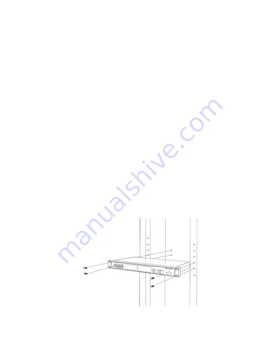
Insert the switch into the 19-inch rack and secure with suitable screws. Make
sure the ventilation holes on the switch are not obstructed.
Step 6
Connect the network cable and supply power to the switch.
Figure 1
Locating a Mounting Bracket


