background image

Digitus Biometrics, Inc.  

User Manual - Models: dbNEXII, dbNEXIII, dbSAI, dbTRI 

Page 7 of 27 


Using the Unit to Gain Access 


All the Digitus Units are configurable as to which credentials are enabled or 

disabled.  


The dbNEXII, dbSAI and dbTRI have 2 credentials, a PIN number and a 

Fingerprint.  


The dbNEXIII also has PIN and Fingerprint, but additionally has the RFID 

credential. 


Which credentials are enabled will determine what is displayed on the LCD. 

Credentials are always requested in the same order. The order is: 


PIN Number 


RFID Card/Token 


Fingerprint 


The LCD will show a message requesting the first enabled credential will. 


If the first enabled credential is PIN, the LCD will display: 


07/04/10 2:00PM 

ENTER ID: [         ] 


If the first enabled credential is RFID, the LCD will display: 


07/04/10 2:00PM 

PRESENT CARD 


If the first enabled credential is Fingerprint, the LCD will display: 


07/04/10 2:00PM 

PLACE FINGER 


Enter or present the first credential, then follow the instructions on the LCD, 

presenting each credential as it's requested. 


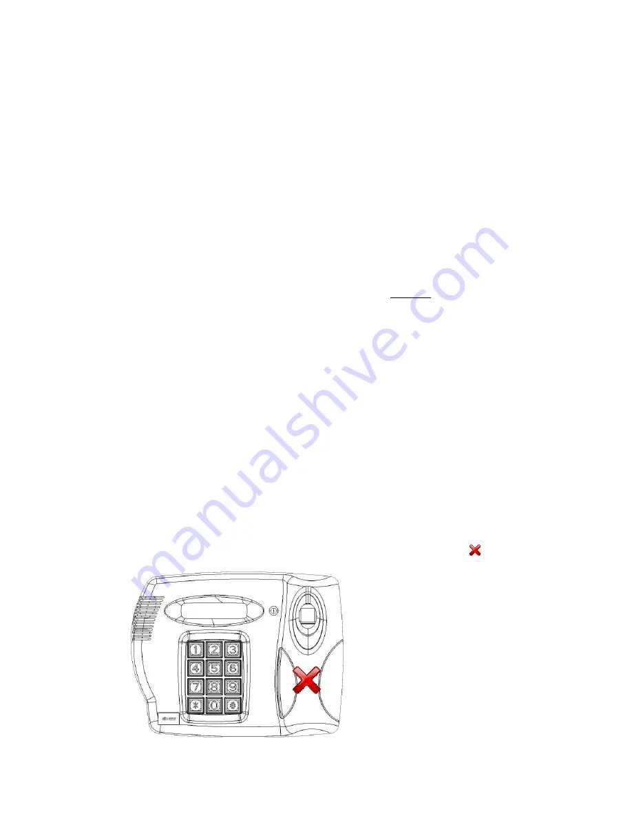
Correct Use of RFID Card/Token 


The RFID Card/Token should be help up to the head unit in the position     showed 

below 


Summary of Contents for dbNEXII

Page 1: ... Manual db Nexus dbNEXII Networked Access Control Solution db Nexus dbNEXIII Networked Access Control Solution db Sentry dbSAI Standalone Access Control Solution db Tracker dbTRI Time and Attendance System ...

Page 2: ...uccessful Access 9 Error Responses 9 Entering the Menu after Initial Setup 9 Entering the Menu after Initial Setup 10 Menu Overview 10 Menu Layout 10 Add a User Via the Menus 11 Edit a User Via the Menus 11 Deleting a User Via the Menus 12 Unit Configuration 13 Setting the Unit s Real time Clock Via the Menus 14 Creating Time Codes Via the Menus 14 Setting the IP Address Via the Menus 16 Appendix ...

Page 3: ...erence to radio or television reception which can be determined by turning the equipment off and on the user is encouraged to try to correct the interference by one or more of the following measures Reorient or relocate the receiving antenna Increase the separation between the equipment and receiver Connect the equipment into an outlet on a circuit different from that to which the receiver is conn...

Page 4: ... This is used for the code hopping encryption that operates between the Head Unit and Control Unit and also between the Control Unit and PC software Note This same password must also be entered into the Management Software so please make a record of the password before entering it Following the 16th digit being entered the Head Unit will display the entered password on the top line of the LCD and ...

Page 5: ...t and straight press 1 on the Head Unit keypad After about 1 second the Head Unit will display PRINT STORED REMOVE FINGER Remove the finger from the fingerprint scanner The Head Unit will then display PLACE FINGER ON SCANNER Place the same finger on the scanner to verify the enrollment The Head Unit will then display PRINT VERIFIED REMOVE FINGER 1 second delay NEW MANAGER ENTER ID 0002 1 second de...

Page 6: ... display PRINT VERIFIED REMOVE FINGER 1 second delay SETUP COMPLETE 1 second delay 01 01 01 00 00 ENTER ID _ The initial setup is now complete Note the date and time will be incorrect These are set via the PC based management software The first enrolled finger is at Index 0001 and the second enrolled finger at Index 0002 The unit can be tested by entering the PIN number on the Head Unit keypad and...

Page 7: ...equested in the same order The order is PIN Number RFID Card Token Fingerprint The LCD will show a message requesting the first enabled credential will If the first enabled credential is PIN the LCD will display 07 04 10 2 00PM ENTER ID If the first enabled credential is RFID the LCD will display 07 04 10 2 00PM PRESENT CARD If the first enabled credential is Fingerprint the LCD will display 07 04...

Page 8: ...g these simple steps will ensure that you have a very high percentage success rate when attempting fingerprint verification or identification Place you finger in the opening as shown below DO NOT SLIDE YOUR FINGER ALONG THE FINGERPRINT SCANNER Place your finger down onto the center of the fingerprint scanner Do not press down hard only apply a slight amount of pressure ...

Page 9: ... the Index specified by the PIN number entered RFID CARD INVALID No user is enrolled at the Index specified by the RFID Card presented RFID CARD NOT FOUND No RFID Card Token was detected RFID CARD NOT IDENTIFIED An RFID Card was found but could not be identified ACCESS DENIED The Fingerprint could not be verified OUTSIDE VALID TIME CODE All the credentials were verified but the user is attempting ...

Page 10: ...unit follow the steps in Setting the IP Address Via the Menus Menu Overview Diagrams of the menus can be found in Appendix 1 The menus are very intuitive and easy to follow If a menu item is asking for a value to be entered it will show you the range of acceptable values If a decision need to be made in the menus 1 Yes and 0 No is the rule to follow Again this will be displayed on the unit s LCD I...

Page 11: ...the instructions to enroll additional fingerprints for the user IT IS RECOMMENEDED THAT AT LEAST 1 FINGER FROM EACH HAND BE ENROLLED Follow the instructions to enroll up to 2 Duress Fingers If a user is being forced to place their finger on a unit to open a door they can use a duress finger to trigger an alert that they are entering under duress For db Nexus and db Tracker systems the alerts will ...

Page 12: ...ser Deleting a User Via the Menus After you enter the menus you will see the following displayed on the Head Unit s LCD User Menu Yes 1 No 0 Press the 1 one key until you see the following displayed Add User Enter ID Press the 0 zero key until you see the following displayed Delete User Enter ID Enter a 4 digit PIN number of the user to be deleted The user is now deleted ...

Page 13: ...urn this feature ON or 0 to turn this feature OFF The propped door delay requires door contacts to be installed If this feature is turned ON you will be prompted to enter the Propped Door Delay next Propped Door Delay 1 99 MIN Use the number keys entering values 1 thru 99 to change the delay period This is the number of minutes the door can be propped open before creating an alarm Security Level 1...

Page 14: ...me Date as requested Choose to Save the new Time Date when prompted Creating Time Codes Via the Menus After you enter the menus you will see the following displayed on the Head Unit s LCD User Menu Yes 1 No 0 Press the 0 zero key until you see the following displayed Time Menu Yes 1 No 0 Press the 0 zero key You will now see the following displayed Set Time Codes Yes 1 No 0 Press the 1 one key You...

Page 15: ...o Blocks of time for a given day If you have cleaning crews who are allowed access only between the hours of 6 00am to 8 00am and 8 00pm to 10 00pm enter data as follows 1st Time Code SUN 06 00 08 00 2nd Time Code SUN 20 00 22 00 After entering the times for Sunday you will be prompted with the following Make MON Same Yes 1 No 0 If you want Monday to have the same times as Sunday press 1 If you wa...

Page 16: ...Yes 1 No 0 If you have a DHCP on your network that will automatically assign the unit an IP address select 1 The unit will then wait for up to 1 minute for the IP address to be assigned If you do not have a DHCP server or would like to specify a static IP address select 0 You will be prompted to enter the IP Address Subnet Mask and Default Gateway Enter IP Address _ _ _ _ _ _ _ _ _ _ _ _ Note each...

Page 17: ...Digitus Biometrics Inc User Manual Models dbNEXII dbNEXIII dbSAI dbTRI Page 17 of 27 Appendix 1 Menu Maps ...

Page 18: ...Digitus Biometrics Inc User Manual Models dbNEXII dbNEXIII dbSAI dbTRI Page 18 of 27 ...

Page 19: ...Digitus Biometrics Inc User Manual Models dbNEXII dbNEXIII dbSAI dbTRI Page 19 of 27 ...

Page 20: ...Digitus Biometrics Inc User Manual Models dbNEXII dbNEXIII dbSAI dbTRI Page 20 of 27 ...

Page 21: ...Digitus Biometrics Inc User Manual Models dbNEXII dbNEXIII dbSAI dbTRI Page 21 of 27 ...

Page 22: ...Digitus Biometrics Inc User Manual Models dbNEXII dbNEXIII dbSAI dbTRI Page 22 of 27 ...

Page 23: ...following message is displayed on the Head Unit LCD CONFIG STATUS FAILED Solution Power the unit down and back up If after powering the unit back up the same message is displayed contact your vendor for support Problem The following message is displayed on the Head Unit LCD SCANNER STATUS INIT FAILED followed by SCANNER STATUS TO CONTINUE Solution There is a problem with the Head Unit microcontrol...

Page 24: ...rmal If you have purchased a unit with RFID there is a problem with the Head Unit microcontroller communicating with the RFID Module It s possible that the cable inside the Head Unit that connects the main PCB to the RFID Module was disturbed during installation The cable should be attached to the connector located at the left edge of the main PCB inside the Head Unit and is labeled RFID Power the...

Page 25: ...nnector is the Control Unit If you are not seeing the specified voltage output of the power supply the power supply needs replacing If the input voltage is correct the input fuse may have blown Remove the fuse from the fuse holder located on the main PCB inside the Control Unit The fuse is labeled BASE 2A SLO BLO Check the fuse with a Ohm Meter to see if it has blown Replace the fuse with a 2Amp S...

Page 26: ...le that connects the Head and Control Units together Ensure the cable is wired straight thru i e Terminal A on the Head is connected to terminal A on the Control Unit terminal B is connected to terminal B etc The 2 wires that are used for the tamper circuit are terminals G and H 2 The Door Sensor Circuit is open Refer to the Door Sensor section of the Installation Manual Ensure that the Jumpers ar...

Page 27: ...blem After entering a password on the Head Unit as described in the Initial Setup section of this manual the status LED turns red and stays red Solution The Head Unit is attempting to send a password to the Control Unit when the Control Unit already has a password The microprocessor in both the Head Unit and Control Unit need to be replaced Please contact your vendor for support Problem The status...

Reviews: