Models: db Nexus II, Nexus III Digitus Biometrics, Inc. 2011
Page 6 of 20
Connecting the Head Unit to the Control Unit
•
Once the control unit and the back plate of the head unit are securely mounted, run a 4-pair (8 conductor) cable
between the head unit and control unit. A Belden 9504 or equivalent should be used.
•
The cable should leave the control unit via one of the push-out holes located on the bottom of the unit, running
neatly along the wall and into the hole drilled through the rear of the head unit. Leave approximately 8”
(200mm) of cable spare at each end to allow for stripping the wires and connection to the terminal blocks. We
also recommend allowing an extra 12” to 18” of cable to be left as a service loop behind the surface you are
mounting to.
•
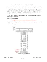
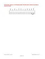
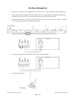
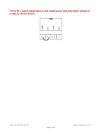
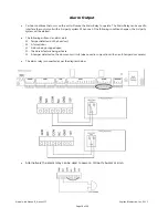
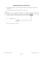
The cable should be wired as shown below. The actual colors are not important but each pair of wires must be
connected as shown in the diagram.
•
Wire the head unit as shown below.
To simplify the wiring the 2-part connectors can be removed from the boards.
•
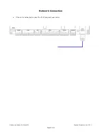
Strip approximately ¼” (6mm) of sheath from each cable and insert into terminal blocks, checking that all wires
are securely fastened.
•
Repeat the procedure at the control unit.


