


Model: db BioLock, db ELock, db iCardLock
Digitus Biometrics, Inc. 2014
Page 4 of 11
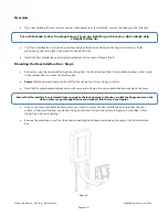
Overview
•
If you are installing the lock into to a cabinet that already has a lock installed, remove the existing lock at this time.
•
The "Door Interface Box" provides an interface between the Remote Node and the fingerprint scanner. It also
provides all power and signal connections to the electric lock.
•
Install the Door Interface Box and electromechanical lock as show in Steps 3 thru 8.
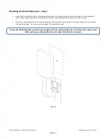
Mounting the Door Interface Box - Step 1
•
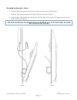
Before removing the double-sided high bond tape from the Door Interface Box, find a suitable location on the inside
of the cabinet door to mount the interface box.
•
Ensure
that the selected location will not affect the cabinet door from closing correctly.
•
Note that for glass paneled cabinet doors with very narrow frames, the only suitable location may be on the glass.
•
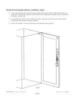
Once you’ve found a suitable location where you intend to mount the Door Interface Box, ensure that the door
surface is clean and free from any debris. (Using neat alcohol to clean the surface is highly recommended. Allow
drying time before proceeding.)
•
Remove the protective cover from the double-sided high bond tape located along the edge of the Door Interface
Box.
Figure 3
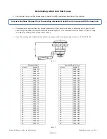
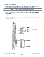
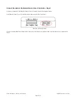
For a db BioLock, follow the steps below. If you are installing a db ELock or db CardLock skip
straight to Step 4a.
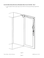
Ensure that the interface box is located close enough to the lock opening in the door, so that the finger-sensor on the
ribbon cable can go through the door and connect into the lock, see Figure 5.