background image

© 2021 Digitrax, Inc.

www.digitrax.com

— 7 —

6.2 Reading and Editing a DS78V's routes:  

As for section 6.1, 

using a suitable DT602 plugged into LocoNet, press the; Menu>3>4 keys to enter 

Route Editor menu.  If any DS78V is on LocoNet, the DT602 will beep after 

about one second and show "DS7x" routes at the D soft key position. 

1.  Press the D soft key to now enter the 

"Selecting DS7x device:" screen,

2.  Rotate the LH encoder knob to under-

line the DS78V to edit routes for.

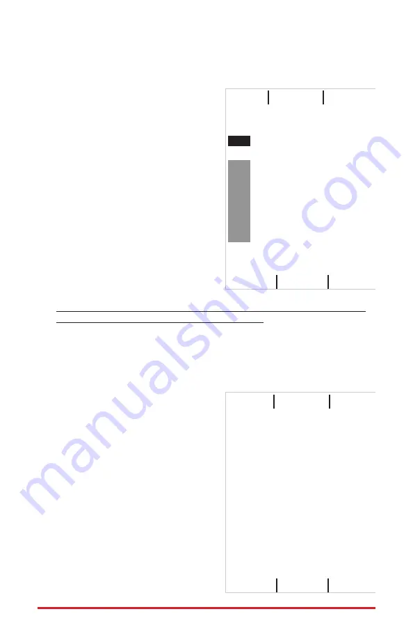
3.  Now press DOWN the LH encoder knob 

to read in and display the Routes of the 

selected DS78V, as shown in adjacent 

"EDIT DS7X Rt#:" screen.

4.  The LH encoder knob now selects a 

Route# and the RH encoder selects the 

black outlined Entry# to edit.  Soft A key 

will toggle the entry from T to C direc-

tion choice. Numeric keys will change 

the SW# in the outlined Entry position. 

"Add" soft key allows inserting another 

entry at current position and "Delete" 

will remove the current entry. The "SW 

test" soft key will send just the outlined 

switch# and direction to LocoNet.

5.  After edit of any Route is complete be sure to press the "Save" soft key  to 

update this DS78V Route to non-volatile memory.  Press "X" to exit.

6.  With LocoNet connected DS78V routes have System wide control ability.

6.3 Programming DS78V CVs on LocoNet: 

As for section 6.0, 

with a suitable DT602, press the; Menu>2>1 keys to enter Operations Mode 

programming.

1.  Press the F "SWITCH" soft key to enter the "Ops Switch" mode program-

ming  screen as shown adjacent.  This 

example screen shows CV11 selected for 

a DS78V with BASE address of SW1.

2.  Use the LH and RH encoder knobs to 

select the SW#/ADR of the DS78V to 

modify a CV on.  A DS78V's CV11 to 

CV15 access the 40 OPSW bit settings.

3.  For example; press the "CVDATA" soft 

key at CV11 to change to CV data entry, 

press the number 6 then press "WRITE".

This now configures the 8 OPSW bits of 

CV11 to 6, forcing this DS78V to change 

to semaphore mode with eight 3-posi-

tion outputs. A value of 02 in CV11 sets 

default 2-position mode. 

4.  Be careful changing the values in 

CV11,12,13,14 and CV15 since the 8 bit 

data number 0-255 in these CV's actu-

EDIT DS7X Rt#:   

01  of 16


Entry# 

TOP of 8

0100

c

0224

t

Thrown

Add

Save

Delete

DS7X Edit: LH knob selects

SW test

CS Rt

     DS78V     

8  # 3122

CV Program Menu A:


CV Number:

    CV data:

0011

0000

Ops Switch ADR: 0001


LOCO

CVNUM CVDATA

DONE

Summary of Contents for DS78V

Page 1: ...wered the green ID LED should light and will briefly wink OFF every 2 secs as a product heartbeat showing the DS78V is opera tional Alternatively power from DCC feeder wires to the TKA B terminals 3 Plug in an active LocoNet to a DS78V RJ12 connector The red OPS LED will light up showing connection Any good LocoNet message seen will cause the DS78V OPS LED to blink OFF briefly With no LocoNet the ...

Page 2: ...ckwise angle for T semaphore STOP RED and full Counter Clockwise for C semaphore CLEAR GREEN as viewed from the arm end of the servo 6 A switch command at Base SW 1 will drive Servo1 to the mid angle or Ap proach position semaphore APPROACH YELLOW for either T or C 7 In this way each servo responds to a consecutive pair of switch commands the first SW as T C and the SW 1 for the Approach setting F...

Page 3: ...om a LocoNet throttle connected PC or DCC track 1 Press and hold the RTS button for about 3 seconds and the ID and OPSW LEDs will blink alternately to show one Route can be set up Release the RTS button 2 Select a switch address on your throttle between 1 and 16 and issue the command direction for Closed This will now be the Route Number you are going to setup Any previous Entries in this Route wi...

Page 4: ...re Input lines The DS78V has sixteen external hardware control lines on two SWITCH SEN SOR IN 10 pin PCB headers using plug in 10 pin ribbon cables The 6 Factory ribbon cable pin 1 edge should be on the right side when plugged in as shown in Figure 1 With Gray cable the red stripe is pin 1 edge and for 10 color cable pin 1 is BROWN with wire colors shown in Tables 2 and 3 If you use these external...

Page 5: ...utput2 is SW11 and the DS message will be Block 11 OCCUPIED 4 A disconnected SENS line will report as UNOCCUPIED 5 The BD4N does not plug directly into a 10 pin header and will not operate Connect the 5 wires used by the BD4N by name via a terminal strip More conveniently you may connect the BD4N through one of two plugged in DSXC4 boards with ribbon cables for true plug and play connectivity This...

Page 6: ... SW pairs instead of 8 T C SW turnout controls 4 The 4th DS78V at Base Sw25 overlaps the 3rd DS78V and so the 3rd SW base is dis played in RED text since SW17 16 would require the 4th DS78V SN9945 to have a base address of at least Sw33 to avoid SW overlaps It shows just SW25 5 Rotate the DT602 LH encoder knob to underline the 4th DS78V line entry after the RED collision marked 3rd DS78V 6 Press t...

Page 7: ...ure to press the Save soft key to update this DS78V Route to non volatile memory Press X to exit 6 With LocoNet connected DS78V routes have System wide control ability 6 3 Programming DS78V CVs on LocoNet As for section 6 0 with a suitable DT602 press the Menu 2 1 keys to enter Operations Mode programming 1 Press the F SWITCH soft key to enter the Ops Switch mode program ming screen as shown adjac...

Page 8: ...aded IPL update since the DS78V does not have a LCD display to show this last IPL download info 4 The OTA and OTB screw terminals are connected to TKA and TKB wires and allow DCC track feed wires to daisy chain between multiple DS78V s 5 A connected DSXCP1 will flash red green while its servo is moving Regulatory Information Declaration of Conformity This device complies with part 15 of the FCC Ru...

Reviews: