background image

3

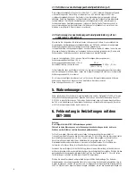
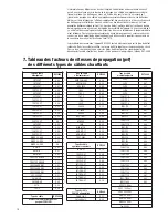
4.1 Pvf defined: 

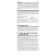
The speed of light in a vacuum is represented by the number 1 (100%). All other signals are
slower. A cable with a pvf of .85 would transmit a signal at 85% of the speed of light. The pvf of
a cable is determined by the dielectric material that separates the two conductors. By entering
the correct pvf, the instrument is calibrated to the particular cable. Typically, the pvf of the cable
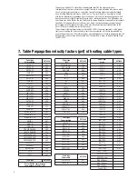
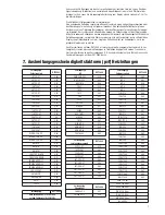
under test will be listed in the cable manufacturer's catalogue. (see table, chapter 7. of this doc-
ument or point your internet browser at: www.tycothermal.com for the most recent version of
this document. In case the pvf of the cable under test is not known it must be determined using
the procedure below. 

4.2 Determining the propagation velocity factor of unknown cable types

Simply measure a length of good cable (no faults) and change the DET-3000´s pvf setting until
the display shows the same distance reading as the measured length. If no good cable is avail-
able, the distance to the fault can be measured from both ends of the cable using an arbitrary
pvf (the same must be used at each end). The actual distance to the fault can be calculated as
in the following example:

Total cable length = 250 m (from records or measured)
Distance measured from first end = 90 m
Distance measured from second end = 140 m
Actual distance from first end =

If required, the instrument can then be reconnected at the first end and the pvf adjusted until
the indicated distance is 97.8 m. This value of pvf can then be noted and used for subsequent
fault location on the same type of cable.
It is also important to know that the velocity factor of a cable can change with temperature and
age. It can also vary from one manufacturing run to another. Even new cable can vary as much
as ± 3%. 

5. Use common sense 

Although a thorough understanding of time domain reflectometry and the measuring instrument
is vital to successful troubleshooting, there is never a substitute for good common sense. If
your DET-3000 indicates a distance of 150 meter to a fault, but there is evidence that a forklift
ran into the pipe at 162 meter, there is a pretty good chance that the fault was caused by the
accident. Familiarity develops versatility. The more you use the DET-3000, the more confident
and comfortable you will become, and the more applications you will find for it. 

6. Locating faults on heat tracing systems

using the DET-3000

The DET-3000 comes with 100 OHM test leads preinstalled NEVER USE THE DET-3000 on
cables connected to the mains supply. Besides the live hazard the voltages at mains level
exposed to the inputs will cause severe damage to the unit.
Prior to each measurement verify that the complete installation is isolated from the mains sup-
ply. Disconnect the heating cable from the connection terminals at the power connection. It is
important that all measurements are performed directly at the heating cable to avoid mis-read-
ings due to power cable used to bring the power to the heating cable. Cold leads permanently
joined with the heating cable, as is the case with MI or other types of series heaters, do not
have to be removed. The final distance readout will have to be adjusted by subtracting the
length of the cold lead.
Connect the leads of the DET-3000 to the cable under test. One lead goes to the conductors,
twisted together in a pig tail, and the other to the braid. Select the appropriate pvf (propagation
velocity factor) from the table (see section 7) depending on the heating cable under test (see
table). Refer to section 4.2 of this manual to determine the pvf of unlisted cables or from cables
from which the pvf is not known.
Select a measuring range exceeding the expected length of the circuit under test. The end of the
cable, or a severe cable fault, is seen on the unit display as a deflection from the horizontal line
across the middle of the screen (in case of doubt start off from the Max range of 3000 m).
Examine the trace for any deflections from the horizontal line after the transmit pulse. Examine
the trace from the left to the right, moving the cursor along the horizontal line to the edge of the
first significant deflection seen. Set the cursor at one pixel to the left of the deflection and read

90

(

90

140

)

X 250    97.8 m

_

~

Summary of Contents for DET-3000

Page 1: ...Quick reference guide Kurzbeschreibung Guide rapide 10 minutes tour 10 Minuten Schnelleinführung Le tour de l appareil en 10 minutes DET 3000 ü www ze gmbh de info ze gmbh de ZIEGLER ENGINEERING ...

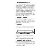
Page 2: ...eration Time domain reflectometers such as the DET 3000 work on the same principle as radar A pulse of energy is transmitted down the cable When that pulse reaches discontinuity such as the end of the cable or a fault along the cable part or all of the pulse energy is reflected back to the instrument The DET 3000 measures the time it takes for the signal to travel down the cable see the discontinu...

Page 3: ... to a fault but there is evidence that a forklift ran into the pipe at 162 meter there is a pretty good chance that the fault was caused by the accident Familiarity develops versatility The more you use the DET 3000 the more confident and comfortable you will become and the more applications you will find for it 6 Locating faults on heat tracing systems using the DET 3000 The DET 3000 comes with 1...

Page 4: ... CT 0 56 10XTV2 CT 0 57 12XTV2 CT 0 56 15XTV2 CT 0 58 20XTV2 CT 0 55 10QTV2 CT 0 39 15QTV2 CT 0 39 20QTV2 CT 0 4 5KTV2 CT 0 58 8KTV2 CT 0 55 15KTV2 CT 0 54 20KTV2 CT 0 51 WGRD FS A 2X 0 44 WGRD FS B 2X 0 43 WGRD FS C 2X 0 4 HWAT L 0 41 HWAT R 0 41 HWAT M 0 42 FROSTOP BLACK 0 50 FROSTOP GREEN 0 51 FREEZGARD W51 0 47 FREEZGARD W52 0 49 FREEZGARD W53 0 48 LC2 5LC2 CT 0 51 EM EM2 R 0 39 EM EM2 XR 0 40...

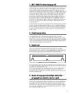
Page 5: ...dar Vom Prüfgerät wird ein elektrischer Impuls durch die elektrische Leitung gesendet Tritt eine Diskontinuität auf wie zum Beispiel an einer schadhaften Stelle oder am Ende einer elektrischen Leitung so wird ein Teil oder der komplette Impuls zum Prüfgerät reflektiert Der Impulsreflekto meter misst dabei die Signallaufzeit welche anschließend in eine Entfernung umgesetzt und im Display als Wellen...

Page 6: ...kann dieser auch von Hersteller zu Hersteller variieren Neue Leitungen können um 3 variieren 5 Wahrnehmungen Außer gründlichem Wissen über die Impulsreflektometrie und das Prüfgerät DET 3000 ist für eine erfolgreiche Fehlerbehebung auch der gesunde Verstand von wesentlicher Bedeutung Wenn Ihr DET 3000 in einer Entfernung von 150 m einen Fehler anzeigt aber es Hinweise darauf gibt dass bei 162 m ei...

Page 7: ... 0 59 8XTV2 CT 0 56 10XTV2 CT 0 57 12XTV2 CT 0 56 15XTV2 CT 0 58 20XTV2 CT 0 55 10QTV2 CT 0 39 15QTV2 CT 0 39 20QTV2 CT 0 4 5KTV2 CT 0 58 8KTV2 CT 0 55 15KTV2 CT 0 54 20KTV2 CT 0 51 WGRD FS A 2X 0 44 WGRD FS B 2X 0 43 WGRD FS C 2X 0 4 HWAT L 0 41 HWAT R 0 41 HWAT M 0 42 FROSTOP BLACK 0 50 FROSTOP GREEN 0 51 FREEZGARD W51 0 47 FREEZGARD W52 0 49 FREEZGARD W53 0 48 LC2 5LC2 CT 0 51 EM EM2 R 0 39 EM ...

Page 8: ...tres temporels tels que le DET 3000 est identique à celui du radar Dans le cas du réflectomètre il consiste à envoyer une impulsion électrique dans le câble à tester Dès que cette impulsion atteint une discontinuité l extrémité du câble par exemple ou une anomalie le long du câble une partie ou la totalité de l énergie d impulsion est réfléchie vers l appareil Le DET 3000 mesure le temps mis par l...

Page 9: ...squ au défaut mais que vous savez qu un chariot élévateur a embouti la canalisation à 162 mètres il y a de fortes chances que le défaut du câble ait pour cause cet accident Plus vous serez familiarisé avec l appareil mieux vous saurez en exploiter les multiples facettes Un usage intensif du DET 3000 vous met tra en confiance et vous fera découvrir de nouveaux champs d application à l appareil 6 Lo...

Page 10: ...2 CT 0 41 10BTV2 CT 0 40 4XTV2 CT 0 59 8XTV2 CT 0 56 10XTV2 CT 0 57 12XTV2 CT 0 56 15XTV2 CT 0 58 20XTV2 CT 0 55 10QTV2 CT 0 39 15QTV2 CT 0 39 20QTV2 CT 0 4 5KTV2 CT 0 58 8KTV2 CT 0 55 15KTV2 CT 0 54 20KTV2 CT 0 51 WGRD FS A 2X 0 44 WGRD FS B 2X 0 43 WGRD FS C 2X 0 4 HWAT L 0 41 HWAT R 0 41 HWAT M 0 42 FROSTOP BLACK 0 50 FROSTOP GREEN 0 51 FREEZGARD W51 0 47 FREEZGARD W52 0 49 FREEZGARD W53 0 48 L...

Page 11: ...24978 Fax 0800 0224993 Norge Tyco Thermal Controls Norway AS Malerhaugveien 25 Postboks 6076 Etterstad 0602 Oslo Tel 47 66 81 79 90 Fax 47 66 80 83 92 Österreich Tyco Thermal Controls N V Lubbeek Office Wien Brown Boveri Strasse 6 14 2351 Wiener Neudorf Tel 0 22 36 86 00 77 Fax 0 22 36 86 00 77 5 Polska Raychem Polska Sp z o o Tyco Thermal Controls ul Farbiarska 69 C 02 862 Warszawa Tel 022 54 52 ...

Reviews: