background image

7

Section 1 - Setting Up

Studio Quad Owner's Manual

4) MIDI IN

- MIDI data is received at this port. When MIDI data is

received, the MIDI indicator in the display flashes on and off.

5) MIDI OUT / THRU

- Merges MIDI data generated by the Studio

Quad with MIDI data received at the input.

6) FOOTSWITCH

- This jack allows connection of the DigiTech FS300

3-button footswitch or any shorting-type footswitch. If using the
DigiTech FS300, button 1 increments through Programs, button 2
decrements through Programs, and button 3 bypasses the Studio
Quad's effects. Using any other single momentary switch device,
the switch acts as a Bypass.

Note:

The footswitch must be plugged in on power up order for the
Studio Quad to detect which type of switch is being used.

7) POWER INPUT

- Connect the included power supply to this jack. It

is a 4-pin DIN connector. Use only the DigiTech PS0920 power
supply with the Studio Quad.

MAKING CONNECTIONS

Because of its flexibility, the Studio Quad can be connected in several
different ways to meet the requirements of specific applications. The fol-
lowing diagrams offer some ways the Studio Quad can be connected.

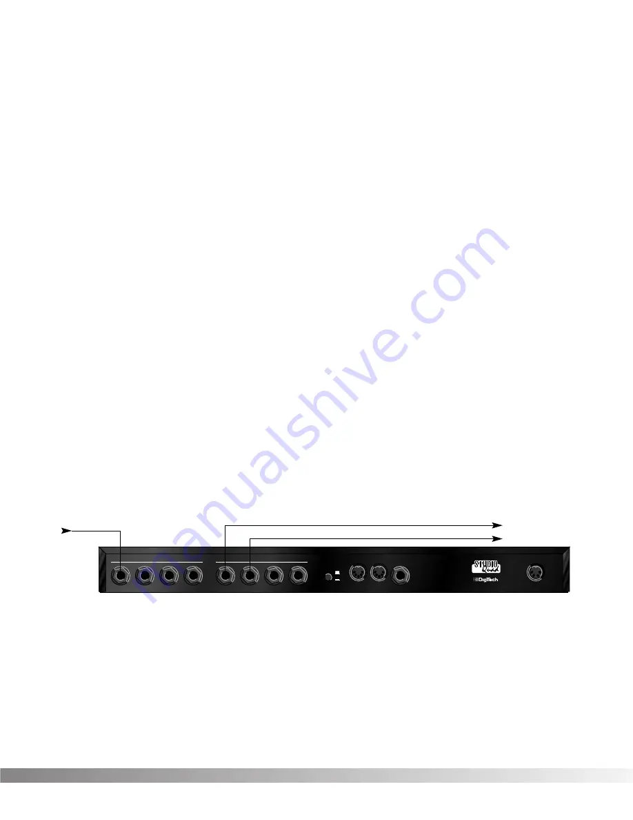
IN LINE:

The Studio Quad can be connected between a line level

instrument output (such as keyboards, recording decks, etc.) and a
line level input (such as mixing console inputs). This method is called
the "in-line" method because the Studio Quad is connected directly in
the audio path of the source. When you use the in-line method, the
master wet-to-dry effects mix is controlled from the Studio Quad oper-
ating system. Cable routings for this method look like Figure 1-3:

Figure 1-3 In-Line Connection

MANUFACTURED IN THE 

USA

 BY

SALT LAKE CITY, UTAH

INPUTS

1

2

3

4

OUTPUTS

1

2

3

4

OUTPUT LEVEL

FOOTSWITCH

POWER

9VAC 2.2A

MIDI

IN

MIDI OUT/

THRU

-10

+4

To Amplifier or Mixer

From Instrument or Direct Source

To Amplifier or Mixer

Summary of Contents for Studio Quad

Page 1: ...ssor A Harman International Company 1 2 F X E d i t P r o g r a m C o m p a r e C o m p a r e 4 I N 4 O U T M U L T I E F F E C T S P R O C E S S O R S D I S C P R O C E S S IN G 1 H a l l 2 R m 3 D l...

Page 2: ...ial hazards with electrical products The lightning flash with arrowpoint in an equilateral triangle means that there are dangerous voltages present within the unit The exclamation point in an equilate...

Page 3: ...an LFO or Dynamic 15 Comparing Programs 16 Storing Programs 17 SECTION 3 EFFECTS AND PARAMETERS About Modules and the Effect Charts 18 About the Charts 19 Reverbs 19 Chorus and Flange 22 Phasers 25 T...

Page 4: ...le for any consequential damage as a result of the product s use in any circuit or assembly 4 Proof of purchase is considered to be the burden of the consumer 5 DigiTech reserves the right to make cha...

Page 5: ...the Studio Quad This means that the AC power line you connect to the Studio Quad should be as free from voltage fluc tuations and RF interference as possible In recording environ ments clean power is...

Page 6: ...Pages available and the Page which is currently selected These icons only appear in the FX Edit and Utilities modes 1d Information Line This row of 24 characters top line of the display is the Informa...

Page 7: ...rough that module s box in the Matrix When in FX Edit mode the box that represents the currently selected effect module will flash Likewise the Modifier module flashes the MODIFIER indicator the Input...

Page 8: ...NNECTIONS The layout of the Studio Quad s simple and straightforward rear panel is illustrated in Figure 1 2 Figure 1 2 Rear Panel 1 AUDIO INPUTS These four inputs can be used for several differ ent c...

Page 9: ...connector Use only the DigiTech PS0920 power supply with the Studio Quad MAKING CONNECTIONS Because of its flexibility the Studio Quad can be connected in several different ways to meet the requireme...

Page 10: ...s improve dramati cally in imaging and spaciousness Figure 1 5 Setting up a mixer s aux sends for true stereo operation Pan Mute 10 0 5 10 20 30 5 L R Mute L R Mute L R Mute L R 5 4 3 2 1 0 1 2 3 4 5...

Page 11: ...offers the flexibility of running different channels in line or in an effects loop REMEMBER Outputs can be configured any way you like so don t let any of this input output stuff scare you A WORD ABOU...

Page 12: ...between Factory or User Programs by pressing the PROGRAM but ton when it is brightly lit The FACTORY PRG or USER PRG indicator will light in the display according to which bank is selected In this mod...

Page 13: ...g to create Once you edit one of the parameters in the FX Module the default name is replaced with the word Custom This means that a default setting has been customized or changed by real time Modifie...

Page 14: ...it an extremely useful and flexible tool for many different applications Programs 1 through 12 in the Factory Program bank represent all the FX module configurations available in the Studio Quad For...

Page 15: ...ads Output Mode Stereo Use the Data Wheel to scroll through the available output config urations Note Make sure you store the settings after you have changed anything See pg 16 for more information US...

Page 16: ...crease the chorus becomes less apparent Ease up on the vocal a little and the chorus increases ALL IN REAL TIME Note Linking a Modifier to a Parameter causes the Parameter to change as if you were cha...

Page 17: ...ure or Aftertouch L 1 LFO1 L 2 LFO2 or DYN Dynamic Note Make sure you store the settings after you made any changes See pg 16 for more information SETTING UP AN LFO OR DYNAMIC MODIFIER To setup an LFO...

Page 18: ...you may find that you want to compare the edited version of the Program to the original stored ver sion Fortunately the Studio Quad provides you with this valuable A B feature in the Compare function...

Page 19: ...se letters 2 to select numbers 3 to delete a character and 4 to insert a blank space When you re finished Press STORE again The top line of the display reads STORE TO followed by the stored name of th...

Page 20: ...lexibility and power than the HLF modules and so on All sizes of FX Modules feature very high quality effects so you don t have to worry if you need to divide the Studio Quad pie four ways For a compl...

Page 21: ...e reflections echo and decay before dying out completely These factors also help determine the audio characteristics of the room such as how long the high frequency reverberations ring when com pared...

Page 22: ...be heard as discrete echoes followed by smoother room reverberations Set DISPERSION low for a dense cluster of reflections during the early portions of DECAY Varies from 1 to 5 Adjusts how quickly the...

Page 23: ...adding reverberations from different parts of the room to each channel Varies from 0 to 99 S t e r e o D u a l R e v e r b G a t e d R e v e r b D u a l R e v e r b S t e r e o R e v e r b R e v e r...

Page 24: ...different pitch voices while the Octal Chorus creates eight voices for extremely full rich sounds The only difference between choruses and flangers is that flangers use less delay and have a feedback...

Page 25: ...e sound you like best Ranges from 99 to 99 WvFrm Selects which waveform the LFO follows Options for this control include sine triangle SP1 Special 1 and SP2 Special 2 The sine wave setting is probably...

Page 26: ...ols the delay time of chorus voices E H Higher delay time settings produce a more dramatic sweeping sound Ranges from 0 to 60 milliseconds Out A B Adjusts the overall level of chorus voice A or B Rang...

Page 27: ...Depth Adjusts the intensity of the phaser effect High settings of DEPTH combined with high settings of FDBCK produce dramatic synth like results Varies from 0 to 100 milliseconds FdBck Controls how m...

Page 28: ...itones to express the shifted note s distance from the original For example with a maximum detune setting of 50 the pitch is exactly one semitone 50 cents up from the original A u t o P a n n e r T r...

Page 29: ...t A B Out A B Adjusts the overall level of pitch shifted voice A or B Ranges from OFF to 100 Pan A B Controls the placement of pitch shifted voice A or B in the stereo image Varies from 99 all left to...

Page 30: ...ces E through H Ranges from 50 to 50 Dly C D Controls the amount of time before detuner voices C and D are heard Ranges from 0 to 60 milliseconds Dly E H Controls the amount of time before detuner voi...

Page 31: ...m delay times differ between 4th HLF and FUL module Types DlyA B Controls the percentage of DELAYTIME allocated to delay voices A and B For example if DELAYTIME above is set to 1000 ms and DLYA is set...

Page 32: ...octave frequencies Boost cut range for each band is from 12 to 12 PARAM DESCRIPTION Equalizers S t e r e o P E Q 3 M o n o P E Q 6 S t e r e o P E Q 6 LoShlv Freq Controls the center frequency of the...

Page 33: ...of the gate less obtrusive Varies from 0 to 2 seconds Hold The setting of HOLD determines how long the gate remains open after the signal level falls below THSHC Long HOLD settings can be used to prev...

Page 34: ...N and SELECT INPUTS 1 THRU 4 You can choose to auto level any combination or all of the inputs Make sure that the program material you want is playing through the inputs then press NEXT PAGE The displ...

Page 35: ...gram changes and CC messages MIDI Channel settings include Off 1 2 15 16 and All To change the MIDI channel assignment do the following Press UTILITY Scroll to Page One of the Utility Menu The display...

Page 36: ...ber will recall the indicated Program number in the Factory bank Pressing 3 again will toggle between the User and Factory banks When you re finished you can return to Program mode by pressing PROGRAM...

Page 37: ...s Using the Data wheel select the Program number you want to dump Note that the AS PRG number changes as you scroll Press 3 and use the Data wheel to select the Program loca tion where you want the Pr...

Page 38: ...are not included in this dump To perform a System Dump do the following Press UTILITY and scroll to Page 5 of the Utility Menu using the NEXT PAGE and PREV PAGE keys The display reads To initiate the...

Page 39: ...n between To change the setting of the Program Autoload function do the follow ing Press UTILITY and scroll to Page 6 of the Utility Menu using the NEXT PAGE and PREVIOUS PAGE keys The display reads U...

Page 40: ...which the unit resets and returns to Program 1 In extreme situations the Studio Quad can be reset using a special power up procedure This will also completely reset the Studio Quad eliminating any cus...

Page 41: ...ds Aux Mes sages Local ON OFF All Notes Off Active Sense Reset Notes Mode 1 OMNI ON POLY Mode 2 OMNI ON MONO Mode 3 OMNI OFF POLY Mode 4 OMNI OFF MONO O Yes X No X X X O O See S Quad SysEx docs X N A...

Page 42: ...Shallow Medium Wide Deep Medium Deep 5Cents 12Cents 5th OctUp 5thUpOctDn 3rd 5thUp Min3 5thUp 4th OctDn OctUp Down OctDownDtn 1 2OctsUp MajChord MinChord Octs Dtn 5th OctDtn 5Octaves Chord Det1 Chord...

Page 43: ...OUT 3 OUT 2 OUT 1 IN 4 IN 3 IN 2 IN 1 OUT 4 OUT 3 OUT 2 OUT 1 IN 4 IN 4 IN 3 IN 2 IN 1 OUT 4 OUT 4 OUT 3 OUT 2 OUT 1 IN 3 IN 2 IN 1 F OUT 3 OUT 2 OUT 1 H H H H H H H 4 4 4 4 4 4 4 4 4 4 4 4 4 4 4 4 4...

Page 44: ...3 Dly 4 Dtn 45 1 Ngt 2 Ngt 3 Ngt 4 Ngt 46 1 GEQ 2 GEQ 3 GEQ 4 GEQ 47 1 Hall 2 Plt 3 Rm 4 GtRv 48 1 Pch 2 Cho 3 Fla 4 Pha 49 1 2 St GEQ8 3 Dly 4 Cho 50 1 Ngt 2 Ngt 3 Plt 4 Dly 51 MFX SpaceVerb 52 MFX R...

Page 45: ...Level 10 dBV 4 dBu software variable Maximum Level 18 dBu Impedance 10 k Output Section Connector 1 4 TS Plug Unbalanced Nominal Level 10dBV 4 dBu switchable Maximum Level 18 dBu Impedance 470 General...

Page 46: ...44 USER NOTES Section 5 Appendix Studio Quad Owner s Manual...

Page 47: ...nal Distribution 3 Overlook Dr Unit 4 Amherst New Hampshire 03031 U S A FAX 603 672 4246 DigiTech Studio Quad and S DISC are registered trademarks of DOD Electronics Corporation Copyright 1995 DOD Ele...

Reviews: